Air conditioning apparatus for vehicles

a technology for air conditioning apparatus and vehicles, which is applied in vehicle heating/cooling devices, vehicle cleaning, vehicle components, etc., to achieve the effects of reducing energy consumption and production costs, simplifying the structure of air conditioning apparatus, and reducing the volume and weight of the apparatus

Active Publication Date: 2014-05-15
HYUNDAI MOTOR CO LTD +2
View PDF3 Cites 4 Cited by
  • Summary
  • Abstract
  • Description
  • Claims
  • Application Information

AI Technical Summary

Benefits of technology

The invention relates an improved vehicle's air-conditioner that has fewer parts than existing systems with multiple doors or drives. This simplifies its design while still providing efficient cooling performance at all times.

Problems solved by technology

This technical problem addressed in this patented describes how current air conditioners have limited options when selecting six types of functions: 1. Hot Air Conditioning Mode - It allows some passengers' windows to get warm without getting wet due to condensations caused by outside temperature conditions during cold weather time. However, these systems require multiple doors to switch between hot/cold settings based solely upon whether there needs them or what they want. Additionally, existing designs allow certain components within the system to become obsolete overtime because new ones may also exist. Therefore, even if just four distinct configurations were available, users would still find themselves unable to adjust their comfort levels accordingly.

Method used


Image

  • Air conditioning apparatus for vehicles
  • Air conditioning apparatus for vehicles
  • Air conditioning apparatus for vehicles

Examples


Embodiment Construction

[0040]Hereinafter, a preferred embodiment of the present disclosure will be described in detail with reference to the attached drawings.

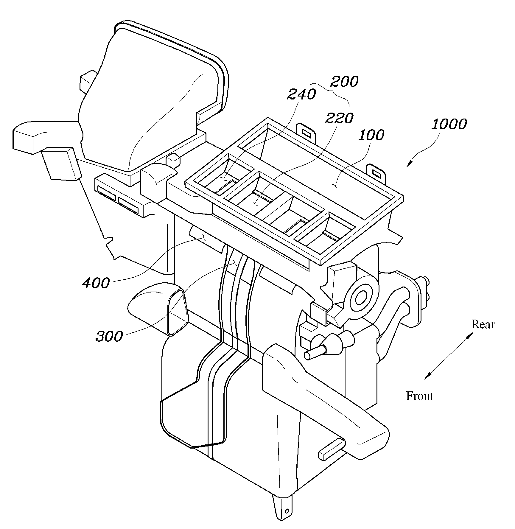
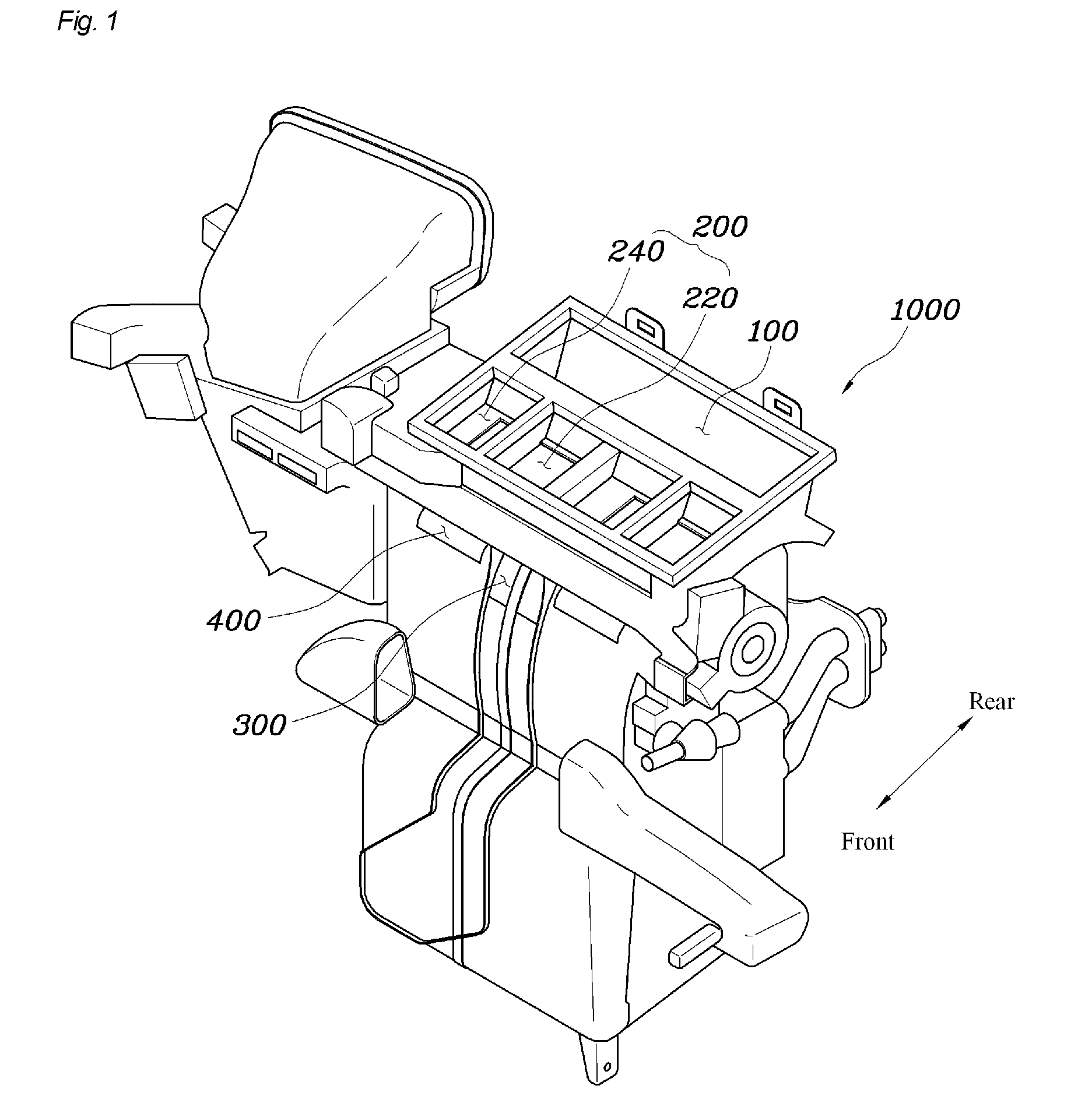
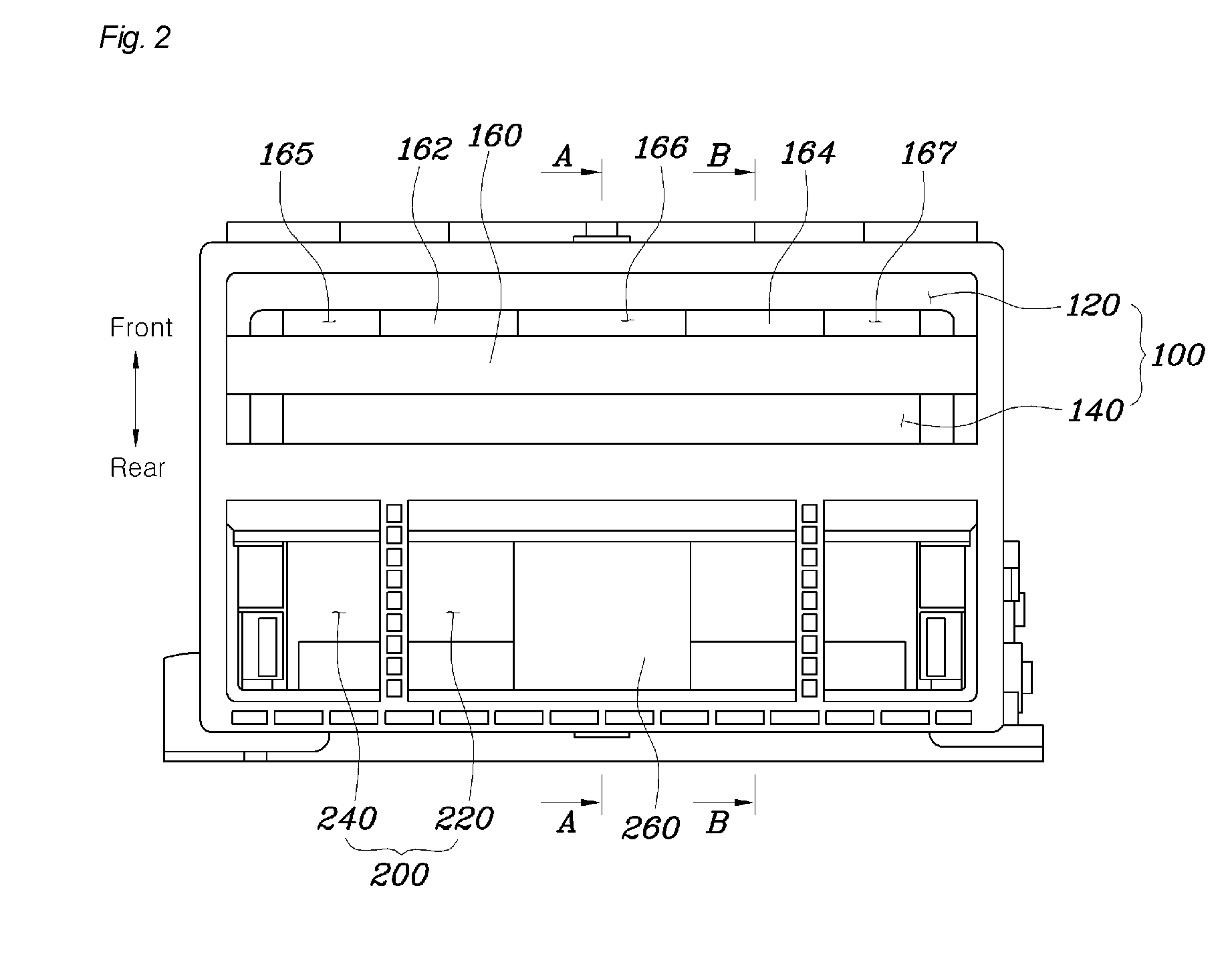
[0041]FIG. 1 is a view illustrating an air conditioning housing 1000 of an air conditioning apparatus for vehicles, according to an exemplary embodiment of the present disclosure. FIG. 2 is a top plan view of the air conditioning housing 1000 of FIG. 1. FIG. 3 illustrates a mode door of the air conditioning apparatus according to the exemplary embodiment of the present disclosure.

[0042]As shown in the drawings, the air conditioning apparatus according to the present disclosure includes the air conditioning housing and the mode door which is installed in or disposed outside the air conditioning housing.

[0043]The air conditioning housing 1000 has a discharge chamber T through which conditioned air is discharged out of the air conditioning housing 1000. A defrost vent 100, a main vent 200, a floor vent 400 and a rear seat vent 300 are formed, in positiona


PUM


Abstract

An air conditioning apparatus includes an air conditioning housing and a mode door. The air conditioning housing has a discharge chamber through which conditioned air is discharged out of the air conditioning housing. The discharge chamber includes a defrost vent, a main vent, floor vents and a rear seat vent. The floor vents are formed on opposite sides of a rear portion of the air conditioning housing. The rear seat vent is formed between the floor vents. The mode door has a front opening hole which is formed in a front portion of the mode door, a pair of main opening holes which are formed in a rear portion of the mode door at positions spaced apart from each other, and a rear-end opening hole which is formed behind a first portion provided between the main opening holes.

Description


Claims


Application Information

Patent Timeline
Owner HYUNDAI MOTOR CO LTD
Why Eureka
Try Eureka