TCOs for Heterojunction Solar Cells

a solar cell and heterojunction technology, applied in the field of photovoltaic devices, can solve the problems of reducing the overall cell cost, limiting the thickness reduction of the wafer, and prone to undesirable bowing and yield loss, so as to improve the control of the uniformity of tco conductivity and interface properties, and reduce the sensitivity to the texture of the wafer

Inactive Publication Date: 2014-09-18
INTERMOLECULAR
View PDF2 Cites 10 Cited by
  • Summary
  • Abstract
  • Description
  • Claims
  • Application Information

AI Technical Summary

Benefits of technology

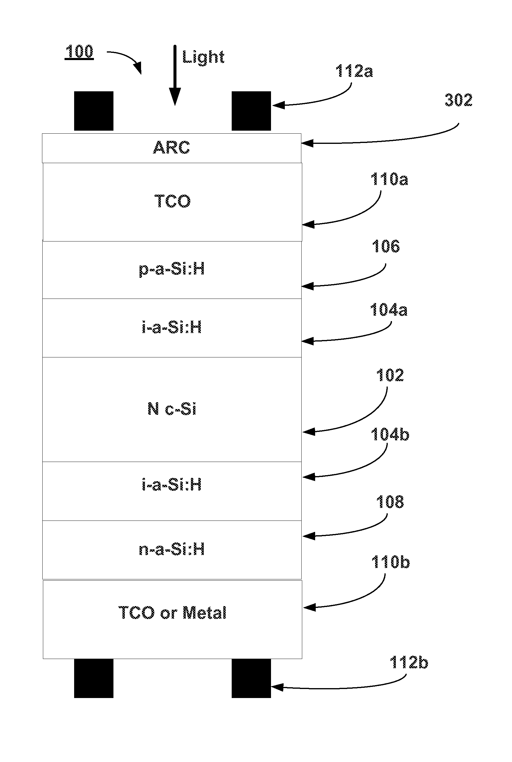
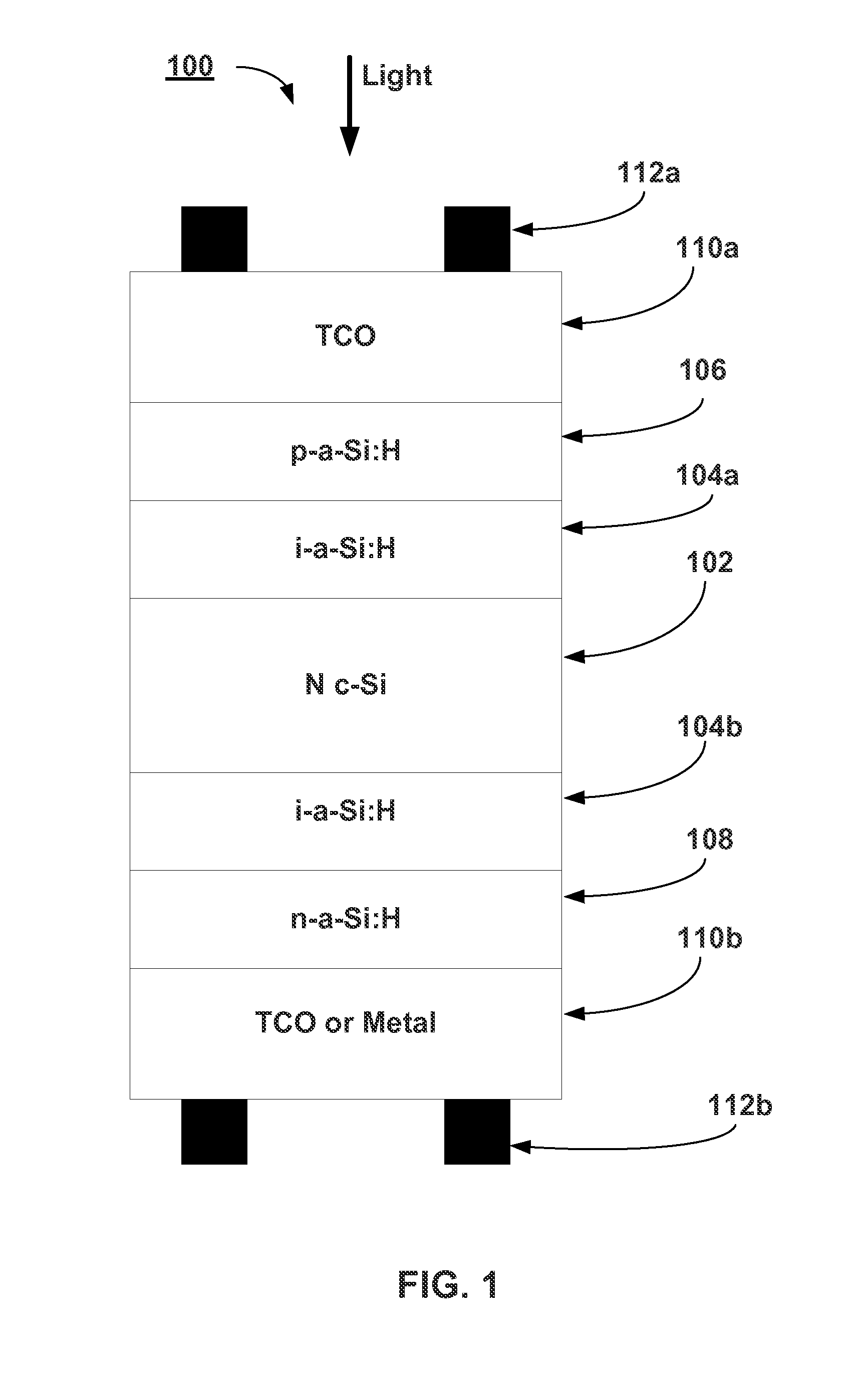
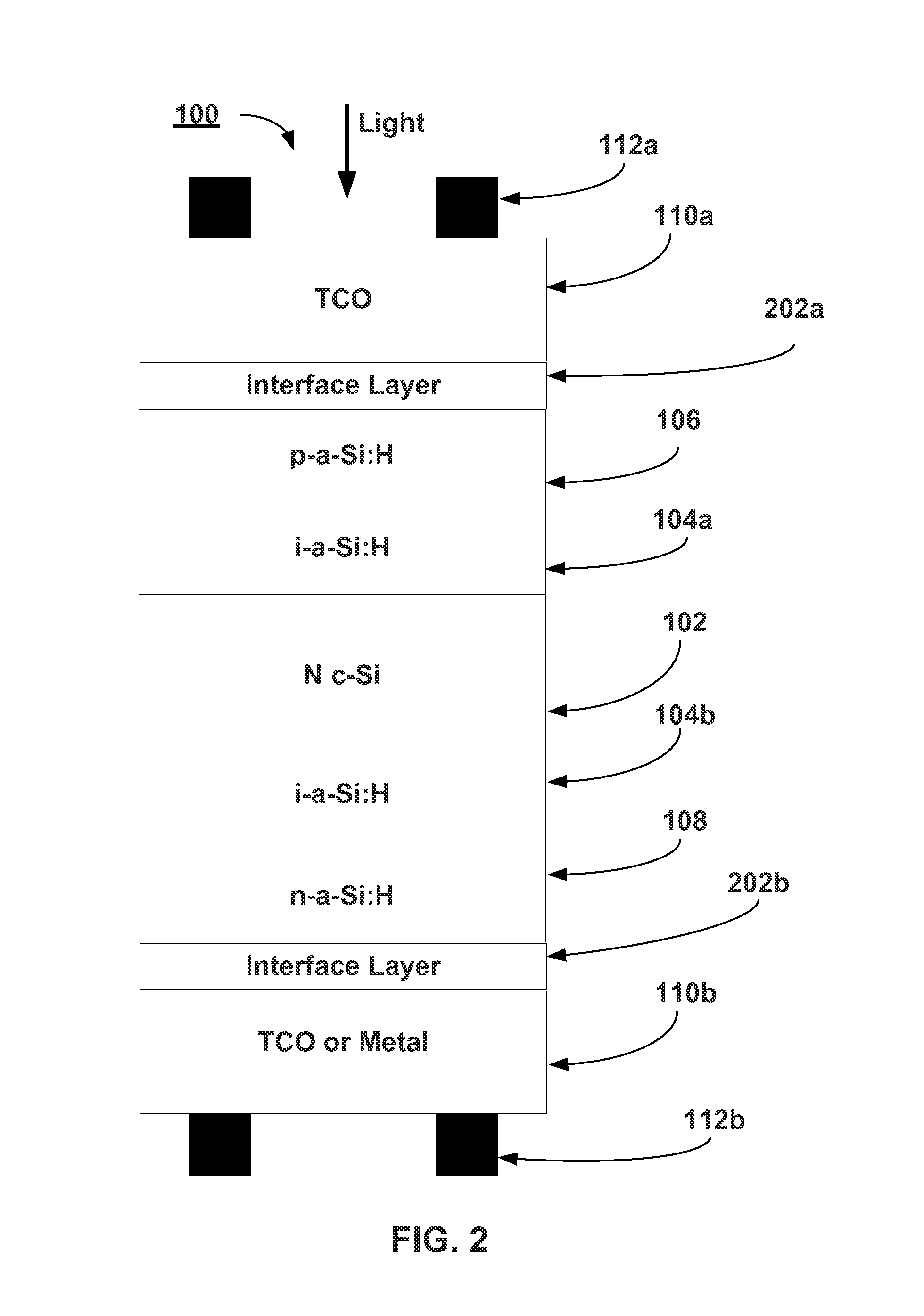
This patented method allows researchers to study how different types of material can be deposited on various substrates like silicon wafers during manufacturing process. By controlling these parameters, they will improve their quality by improving consistency between electrical conduction and surface characteristics while reducing variations from other sources such as impurities or imperfections found at specific points along its path through production line. These techniques help optimize performance and efficiency of photovoltaic devices made with this type of layered structure.

Problems solved by technology

This patented technical problem addressed in this patents relates to finding novel ways to improve the properties of solar cells while minimizing their impact upon manufacturability issues or costs associated with current production techniques like chemical vapor deposited growth methodology.

Method used


Image

  • TCOs for Heterojunction Solar Cells
  • TCOs for Heterojunction Solar Cells
  • TCOs for Heterojunction Solar Cells

Examples


Embodiment Construction

[0013]A detailed description of one or more embodiments is provided below along with accompanying figures. The detailed description is provided in connection with such embodiments, but is not limited to any particular example. The scope is limited only by the claims and numerous alternatives, modifications, and equivalents are encompassed. Numerous specific details are set forth in the following description in order to provide a thorough understanding. These details are provided for the purpose of example and the described techniques may be practiced according to the claims without some or all of these specific details. For the purpose of clarity, technical material that is known in the technical fields related to the embodiments has not been described in detail to avoid unnecessarily obscuring the description.

[0014]As used herein, the notations “Al:ZnO” and “ZnO:Al” will be understood to be equivalent and will describe a material wherein the base material is the metal oxide and the el


PUM


Abstract

Methods are used to develop and evaluate new materials and deposition processes for use as TCO materials in HJCS solar cells. The TCO layers allow improved control over the uniformity of the TCO conductivity and interface properties, and reduce the sensitivity to the texture of the wafer. In Some embodiments, the TCO materials include indium, zinc, tin, and aluminum.

Description


Claims


Application Information

Patent Timeline
Owner INTERMOLECULAR
Why Eureka
Try Eureka