Vacuum pump connecting apparatus and method for installing vacuum pump connecting apparatus

Active Publication Date: 2014-10-02
EBARA CORP
View PDF8 Cites 4 Cited by
  • Summary
  • Abstract
  • Description
  • Claims
  • Application Information

AI Technical Summary

Benefits of technology

[0036]When the evacuation connection portion has a magnetic shielding member, the adverse effect of magnetism from the vacuum pump can be further reduced.
[0037]When the vacuum pump is fixed, on a side of the vacuum pump opposite to the intake port, to a structure joined to a base on which the electron beam application apparatus is installed, or when the coupling member is fixed to the structure at the second end of the first vibration absorbing portion, or when the coupling member is fixed to the structure at the second end of the second vibration absorbing portion, both the elastic connection between the lens barrel portion and the vacuum pump and the rigid fixation of the pump can be achieved.

Problems solved by technology

However, the vacuum pump is suspended by the bellows with low rigidity, and thus, the needed attachment strength fails to be obtained when the pump abnormality described in (3) occurs, leading to a dangerous situation.
Moreover, the magnetic-bearing turbomolecular pump is susceptible to external vibration with a low frequency, and the configuration A in which the magnetic-bearing turbomolecular pump is less rigidly suspended offers low resistance to external vibration.
Furthermore, in the configuration A, since the vacuum pump is suspended, an area of the lens barrel portion which can be evacuated is limited to the upper part of the lens barrel portion.
Hence, a lower part of the lens barrel portion fails to be evacuated or the distance between the pump intake port and the lower part of the lens barrel portion to be evacuated increases, precluding the evacuation performance of the pump from being fully delivered.

Method used


Image

  • Vacuum pump connecting apparatus and method for installing vacuum pump connecting apparatus
  • Vacuum pump connecting apparatus and method for installing vacuum pump connecting apparatus
  • Vacuum pump connecting apparatus and method for installing vacuum pump connecting apparatus

Examples


Example

[0046]Embodiments of the present invention will be described below with reference to the drawings.

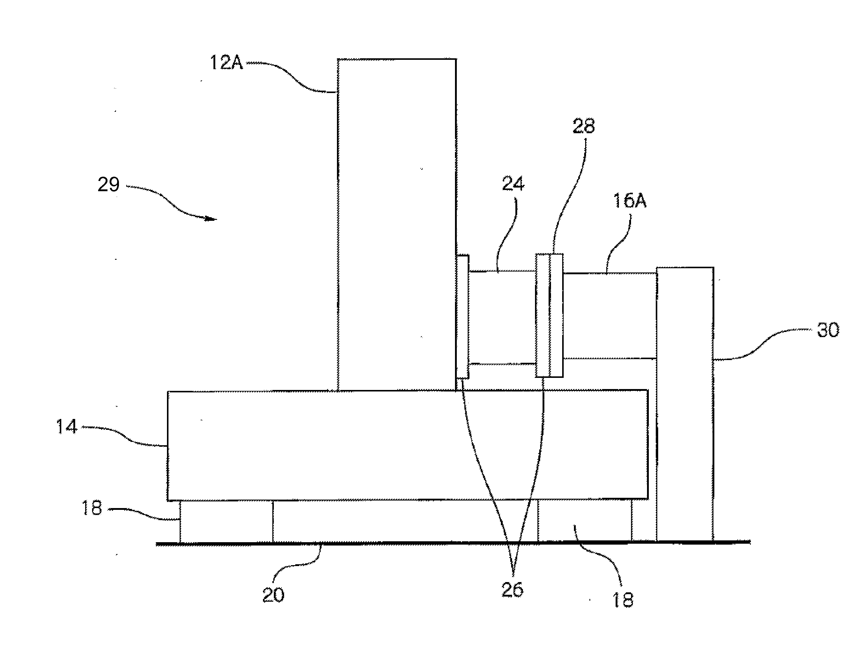
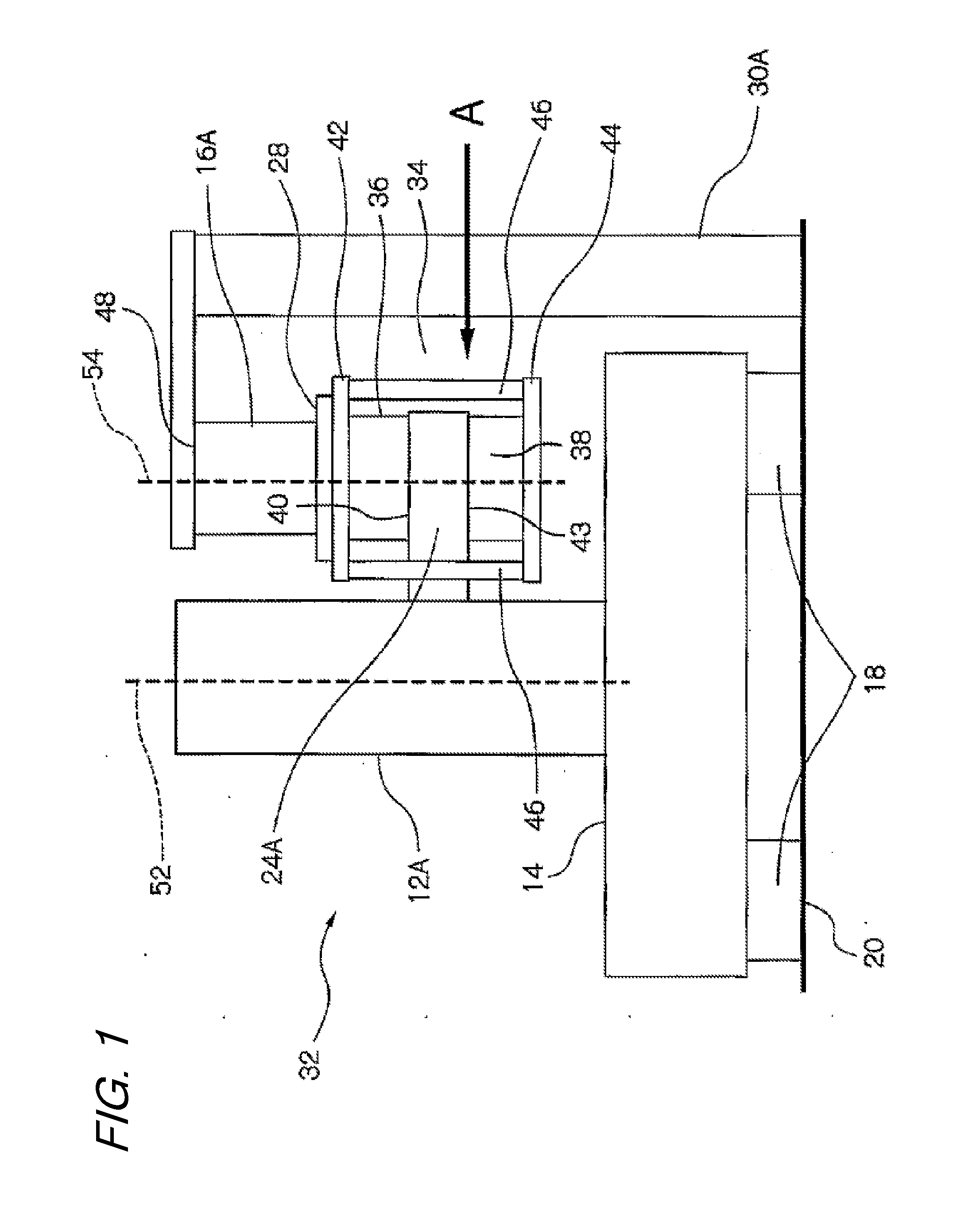
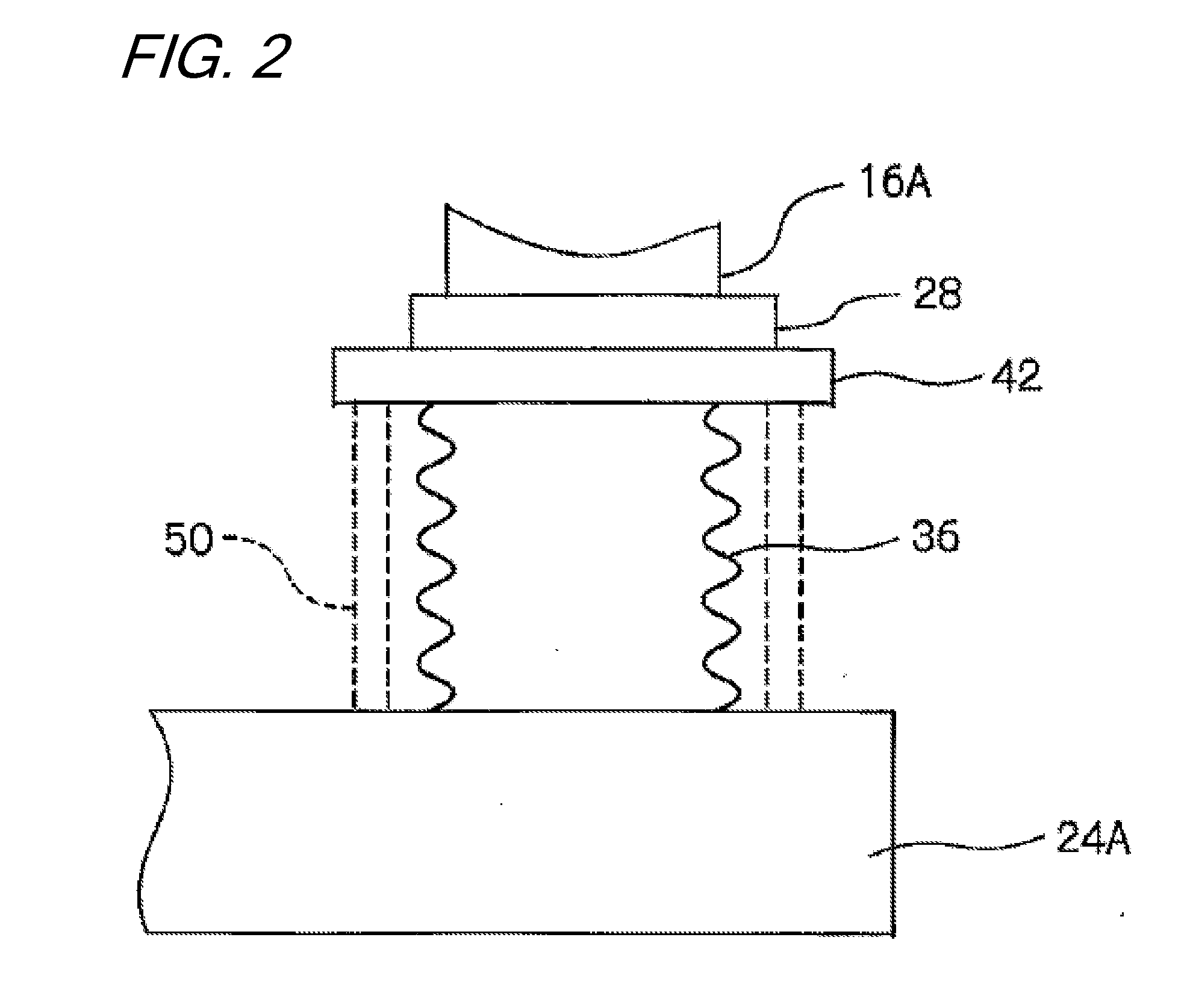
[0047]FIG. 1 is a front view of an electron beam application apparatus 32 and a vacuum pump connecting apparatus 34 showing an embodiment of the present invention. A vacuum pump 16A has an intake port 28 and an exhaust port. The vacuum pump 16A sucks, through the intake port 28, a gas in a lens barrel portion 12A of the electron beam application apparatus 32 which is to be evacuated, and discharges the gas through the exhaust port. The vacuum pump connecting apparatus 34 includes an evacuation connection portion 24A that connects the intake port 28 of the vacuum pump 16A to the lens barrel portion 12A.

[0048]The vacuum pump connecting apparatus 34 has a first vibration absorbing portion 36 and a second vibration absorbing portion 38 which are connected to the evacuation connection portion 24A so that the first vibration absorbing portion 36 and the second vibration absorbing portion 38 lie


PUM


Abstract

A vacuum pump connecting apparatus has a first vibration absorbing portion and a second vibration absorbing portion which are connected to an evacuation connection portion so as to dispose the first vibration absorbing portion and the second vibration absorbing portion opposite each other via the evacuation connection portion. The first vibration absorbing portion is connected to an intake port of a vacuum pump at a second end of the first vibration absorbing portion opposite to a first end of the first vibration absorbing portion connected to the evacuation connection portion. The first vibration absorbing portion and the second vibration absorbing portion are elastic bellows. A vacuum pump connecting apparatus has a rigid coupling member is connected to a second end of the second vibration absorbing portion opposite to a first end of the second vibration absorbing portion connected to the evacuation connection portion.

Description


Claims


Application Information

Patent Timeline
Owner EBARA CORP
Why Eureka
Try Eureka