Fingerprint recognition control methods for payment and non-payment applications

Active Publication Date: 2016-02-18
EGIS TECH
View PDF6 Cites 15 Cited by
  • Summary
  • Abstract
  • Description
  • Claims
  • Application Information

AI Technical Summary

Benefits of technology

[0008]In an exemplary embodiment, an electronic device is provided. The electronic device comprises a first memory unit for storing a non-payment application, a first processor, a fingerprint sensing unit and a security element. The security element is coupled to the fingerprint sensing unit, and comprises a second processor and a second memory unit for storing a payment application, first user fingerprint information and second user fingerprint information. When the second processor executes the payment application, the fingerprint sensing unit captures a fingerprint image of a user's finger and the second processor transmits the captured fingerprint image to the first processor via a secure channel. The first processor calculates biometric characteristics of the fingerprint image to generate to-be-recognized fingerprint information, and transmits the to-be-recognized fingerprint information to the second processor via the secure channel. The second processor further determines whether the to-be-recognized fingerprint information matches the second user fingerprint information. When the second processor determines that the to-be-recognized fingerprint information matches the second user fingerprint information, the second processor generates an authentication signal for a payment transaction.
[0009]In another exemplary embodiment, a fi

Problems solved by technology

However, the computation ability of the conventional security element is very limited.
If the fingerprint recognition required by the payment tra

Method used


Image

  • Fingerprint recognition control methods for payment and non-payment applications
  • Fingerprint recognition control methods for payment and non-payment applications
  • Fingerprint recognition control methods for payment and non-payment applications

Examples


Embodiment Construction

[0016]The following description is of the best-contemplated mode of carrying out the invention. This description is made for the purpose of illustrating the general principles of the invention and should not be taken in a limiting sense. The scope of the invention is best determined by reference to the appended claims.

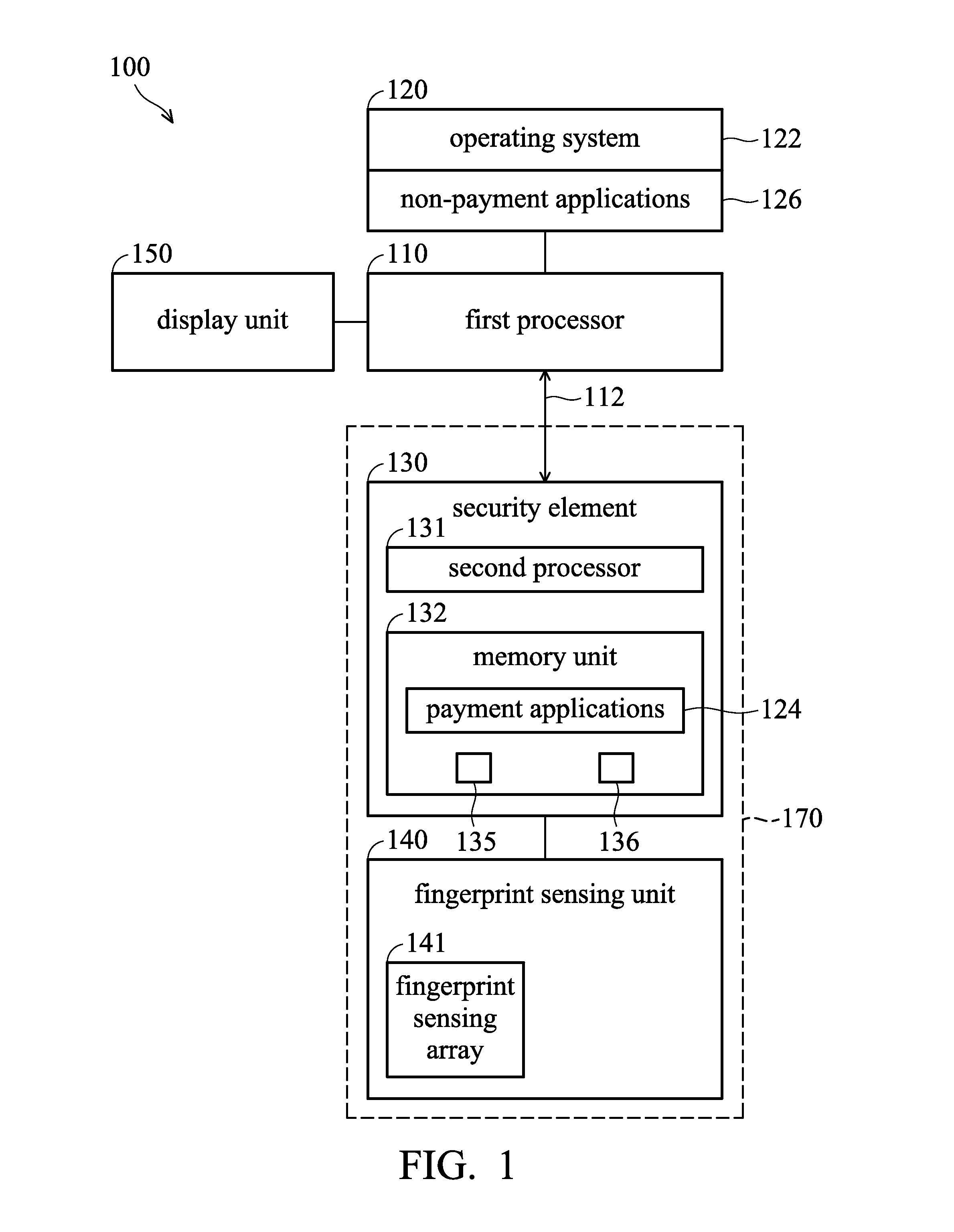
[0017]FIG. 1 is a block diagram of an electronic device in accordance with an embodiment of the invention. The electronic device 100, for example, may be a cellular phone, a smartphone, or a tablet PC. In an embodiment, the electronic device 100 comprises a first processor 110, a memory unit 120, a security element 130, a fingerprint sensing unit 140 and a display unit 150. The memory unit 120 stores an operating system 122 and application software including non-payment applications 126 for execution by the first processor 110. The security element 130 is a tamper-resistant platform (typically a one chip secure microcontroller) capable of securely hosting applications and


PUM


Abstract

An electronic device is provided. The electronic device includes a first memory unit for storing a non-payment application, a first processor, a fingerprint sensing unit and a security element including a second memory unit and a second processor. The second memory unit stores a payment application and user fingerprint information. When the second processor executes the payment application, the fingerprint sensing unit captures a fingerprint image of a user's finger and the second processor transmits the fingerprint image to the first processor via a secure channel. The first processor calculates biometric characteristics of the fingerprint image to generate to-be-recognized fingerprint information which is transmitted to the second processor via the secure channel. When the second processor determines that the to-be-recognized fingerprint information matches the user fingerprint information, the second processor generates an authentication signal for a payment transaction.

Description


Claims


Application Information

Patent Timeline
Owner EGIS TECH
Why Eureka
Try Eureka