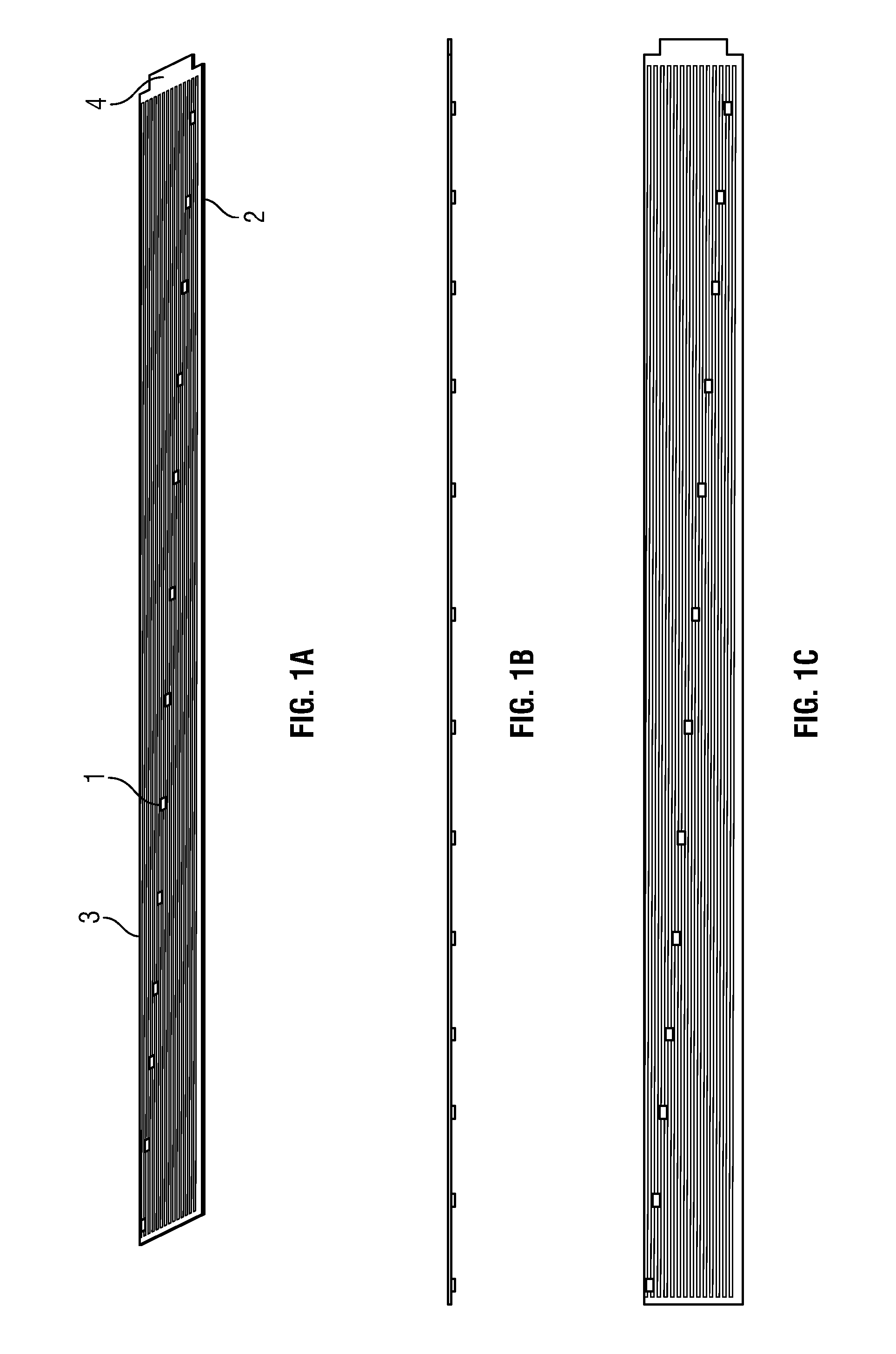
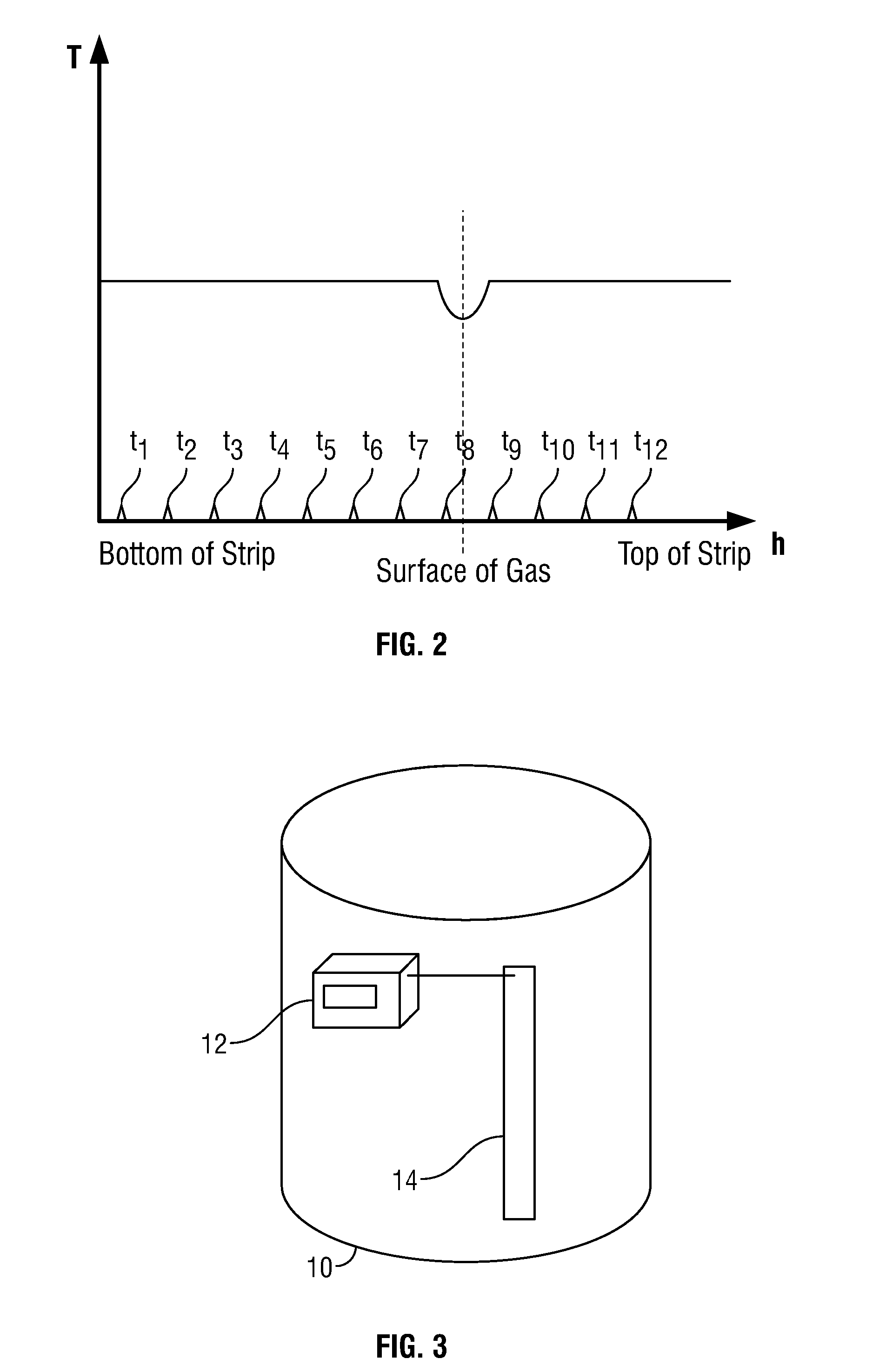
[0007]Due to the fact that the temperature sensors detect a temperature drop which occurs as a result of the release of gas from the canister, there is no need to utilise heating elements to heat up the surface of the canister, which would be required before measuring the temperature of the surface of the canister if a temperature difference were to be observed when the canister is not in use, and has not been used for some time. It will be appreciated that this reduces the cost of the system, because heating elements can be omitted, and also removes the safety problems associated with generating heat in the proximity of a gas supply.
[0008]The detection circuitry may monitor the outputs of the temperature sensors on a periodic basis, the interval of which is dependent on whether the detection circuitry has recently detected that a subset of the temperature sensors is measuring a lower temperature than the remainder of the temperature sensors. This reduces overall power consumption by reducing the power consumption when the gas canister is not currently in use. The detection circuitry may periodically monitor the outputs of the temperature sensors at a first, fixed, interval when the detection circuitry is detecting that a subset of the temperature sensors is measuring a lower temperature than the remainder of the temperature sensors, and when the detection circuitry determines that the subset of the temperature sensors is no longer measuring a lower temperature than the remainder of the temperature sensors, the detection circuitry may transition to monitoring the outputs of the temperature sensors at a second, progressively increasing, interval. The second, progressively increasing, interval may reach a maximum interval length after the subset of temperature sensors has not measured a lower temperature than the remainder of the temperature sensors for a predetermined period of time. The detection circuitry may be responsive to detecting that a subset of the temperature sensors are measuring a lower temperature than the remainder of the temperature sensors to generate a notification that the canister is currently in use. This function can be provided since a temperature drop at the liquid/gas interface within the canister will only occur while the gas canister is in use, and shortly afterwards (until the system returns to thermal equilibrium). The detection circuitry may be operable determine a rate of gas consumption from the identified level of liquefied gas within the canister measured at a plurality of different times. This results in a gas consumption rate which becomes progressively more accurate as the liquid gas level moves past several temperature sensors over a period of time. The detection circuitry may be operable to estimate a usage time remaining for the canister based on the determined rate of gas consumption. In some embodiments, the detection circuitry may be operable to determine a current rate of gas consumption from the magnitude of the temperature drop measured from the subset of the temperature sensors and the remaining temperature sensors. This provides a very fast indication of gas consumption, but may be relatively unreliable and inaccurate. However, if the determined current rate of gas consumption exceeds a predetermined threshold, the detection circuitry may generate an alert notification. This could be the case where the gas consumption is determined to exceed safe levels, or at least to be at risk of being at an unsafe level based on the temperature drop measured. Further, if the determined current rate of gas consumption exceeds a predetermined threshold, the detection circuitry may control a valve on the canister to stop releasing gas. This could be used to provide an automatic shut off of a gas canister in the event that a risk of unsafe gas consumption rates is detected. Also, as the device uses temperature sensors, if the bottle is determined to become too hot, or the monitoring device itself malfunctions and becomes hot, the device can shut down in response, warn the user and shut off any valves. In some embodiments, it could also communicate with a smartphone app or the like.
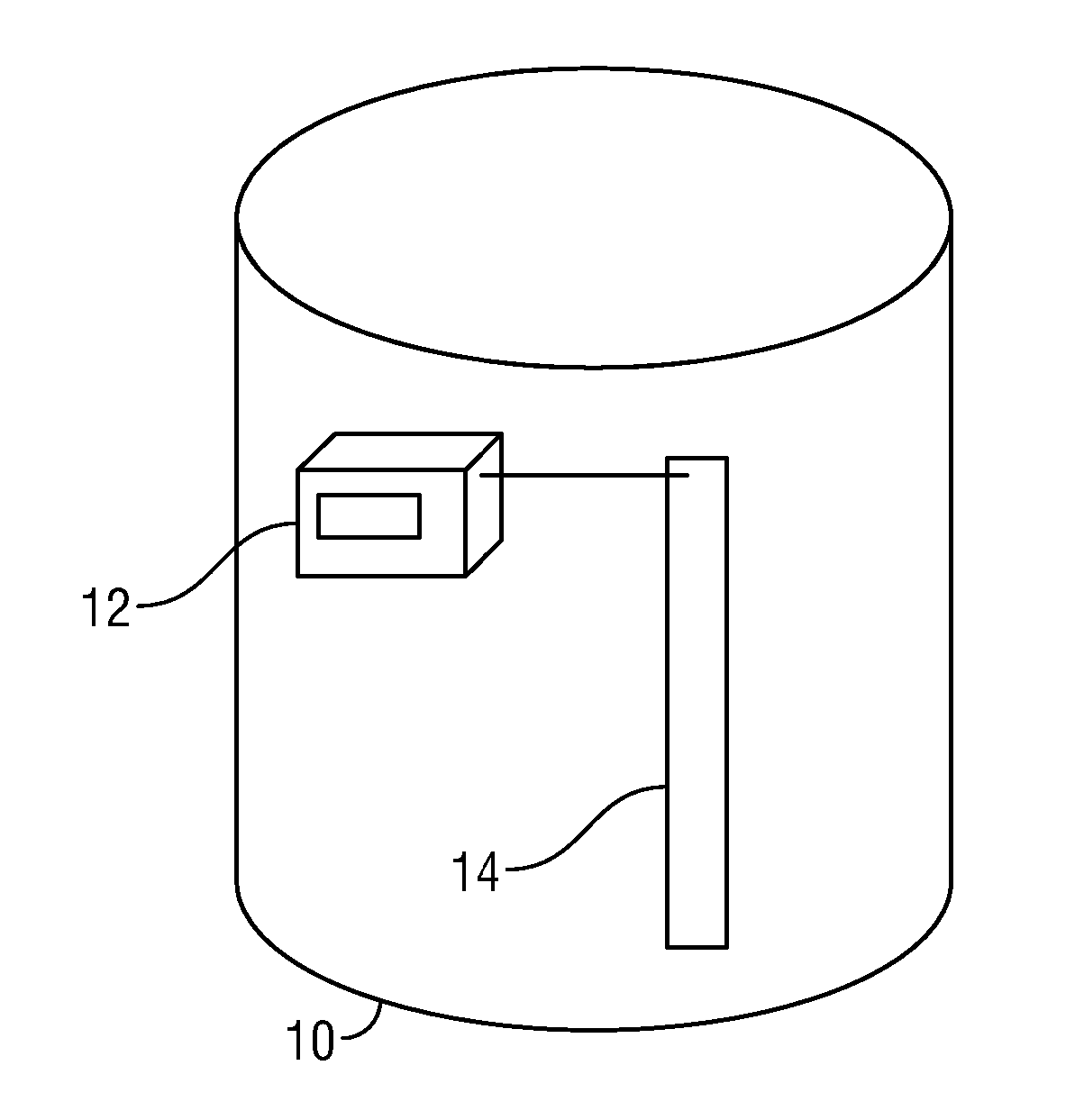
[0009]According to another aspect of the present invention, there is provided a measurement system comprising a measurement device as described above, and a display device, wherein the measurement device is operable to provide the identified level of liquefied gas to the display device, and the display device is operable to display the received identified level of liquefied gas. In one embodiment the measurement device is electrically connected to the display device, and the identified level of liquefied gas is provided via the electrical connection. In other words, a single integral unit may be provided which both determines gas level (and optionally consumption), and also displays it. In another embodiment, the measurement device is wirelessly connected to the display device, and the identified level of liquefied gas is provided via the wireless connection. In other words, a separate display (user interface) device may be provided, potentially at a position remote from the canister. For example, the display device may be fitted inside a caravan, while the gas canister may be external to the caravan. The display device may also be a smartphone, or other personal device, instead of a dedicated stand-alone unit. The measurement device may be operable to transmit the identified level of liquefied gas to the display device via the wireless connection only when the measurement device is currently detecting that the subset of temperature sensors are measuring a lower temperature than the remainder of the temperature sensors. This reduces power consumption at the measurement device by only transmitting to the display device when there is new, useful, information. The wireless connection may be unidirectional from the measurement device to the display device. This permits a reduction in the complexity of the system, resulting in cost savings. The display device may be operable to display one or both of a current level of the liquefied gas in the canister, and a usage time remaining based on current and/or past usage. The display device may be responsive to the non-receipt of a communication from the measurement device for a predetermined period of time to display a message notifying the user. The user is then able to check the battery on the measurement device. While embodiments of the present invention are advantageous in that they can be retrofitted to existing canisters, the measurement device may instead be integrated into the body of a canister. A canister comprising the measurement device as described above is therefore envisaged as a further aspect of the present invention.
[0010]In order to provide improved accuracy and reliability, the detection circuitry may be operable to calculate a line of best fit from the temperature measurements taken by the array of temperature sensors, and to identify the current fill level from the line of best fit. The line of best fit may be a cubic line of best fit generated by multiplying the temperature measurements taken by the array of temperature sensors with a predetermined matrix to obtain a set of coefficients for the cubic line of best fit. The detection circuitry may be operable to compare a gradient of the line of best fit with a predetermined threshold to identify one or both of (a) whether the canister is in use, and (b) whether a valid fill level can be taken from the line of best fit.


