Connector

a technology of connecting rods and contacts, applied in the direction of coupling contact members, coupling device connections, electrical equipment, etc., can solve problems such as loss increase, and achieve the effect of suppressing the reduction of impedan

Active Publication Date: 2016-08-04
PANASONIC INTELLECTUAL PROPERTY MANAGEMENT CO LTD
View PDF20 Cites 4 Cited by
  • Summary
  • Abstract
  • Description
  • Claims
  • Application Information

AI Technical Summary

Benefits of technology

The connector described in this patent helps prevent interference between contact pairs when they are aligned correctly. It also prevents incorrect connections during assembly.

Problems solved by technology

The technical problem addressed by this patent is how to reduce signal interference caused by misaligned contacts during connection due to narrower contact pitch for smaller electronic devices.

Method used


Image

  • Connector
  • Connector
  • Connector

Examples


Embodiment Construction

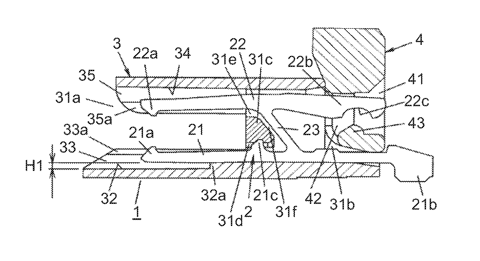
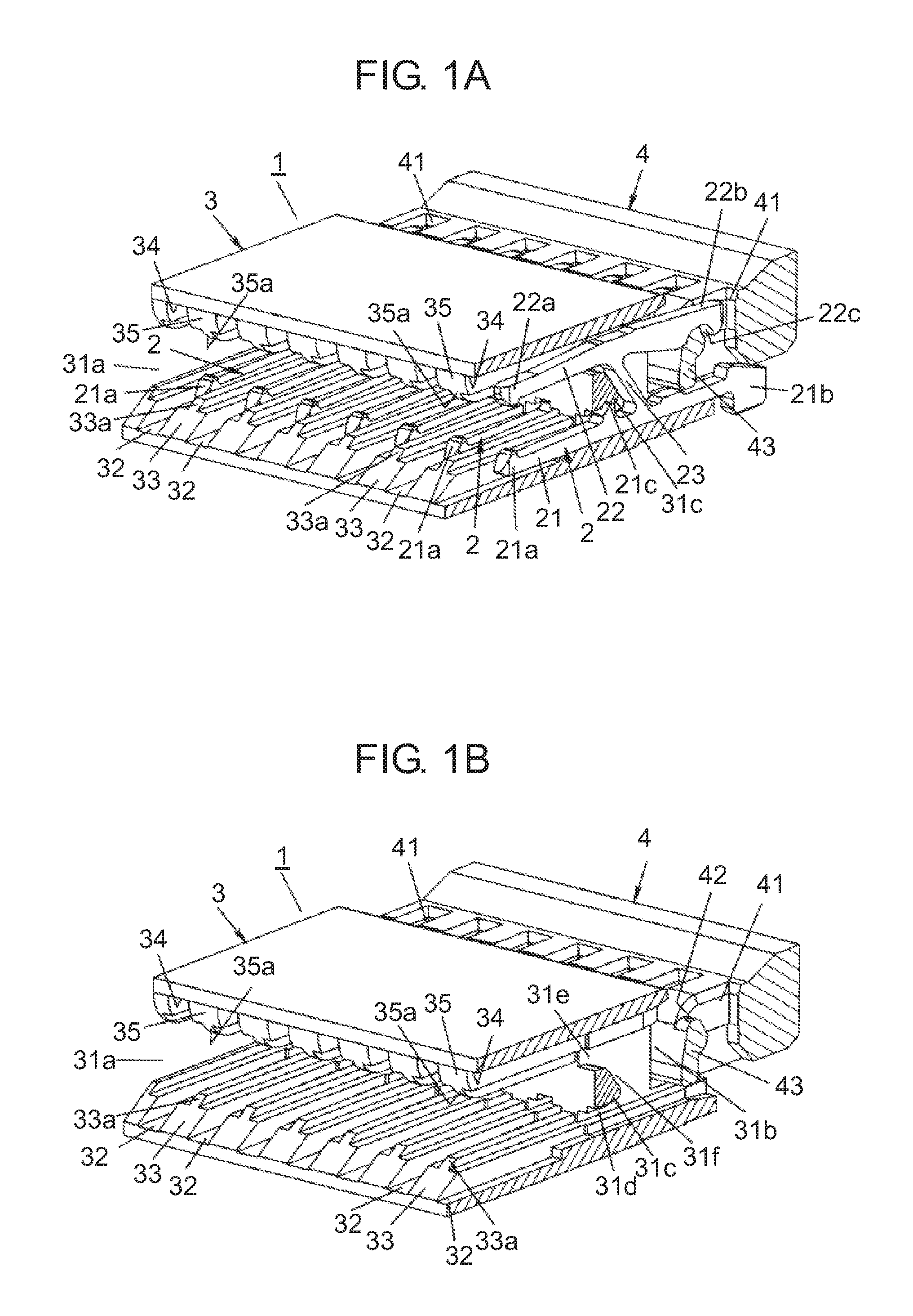
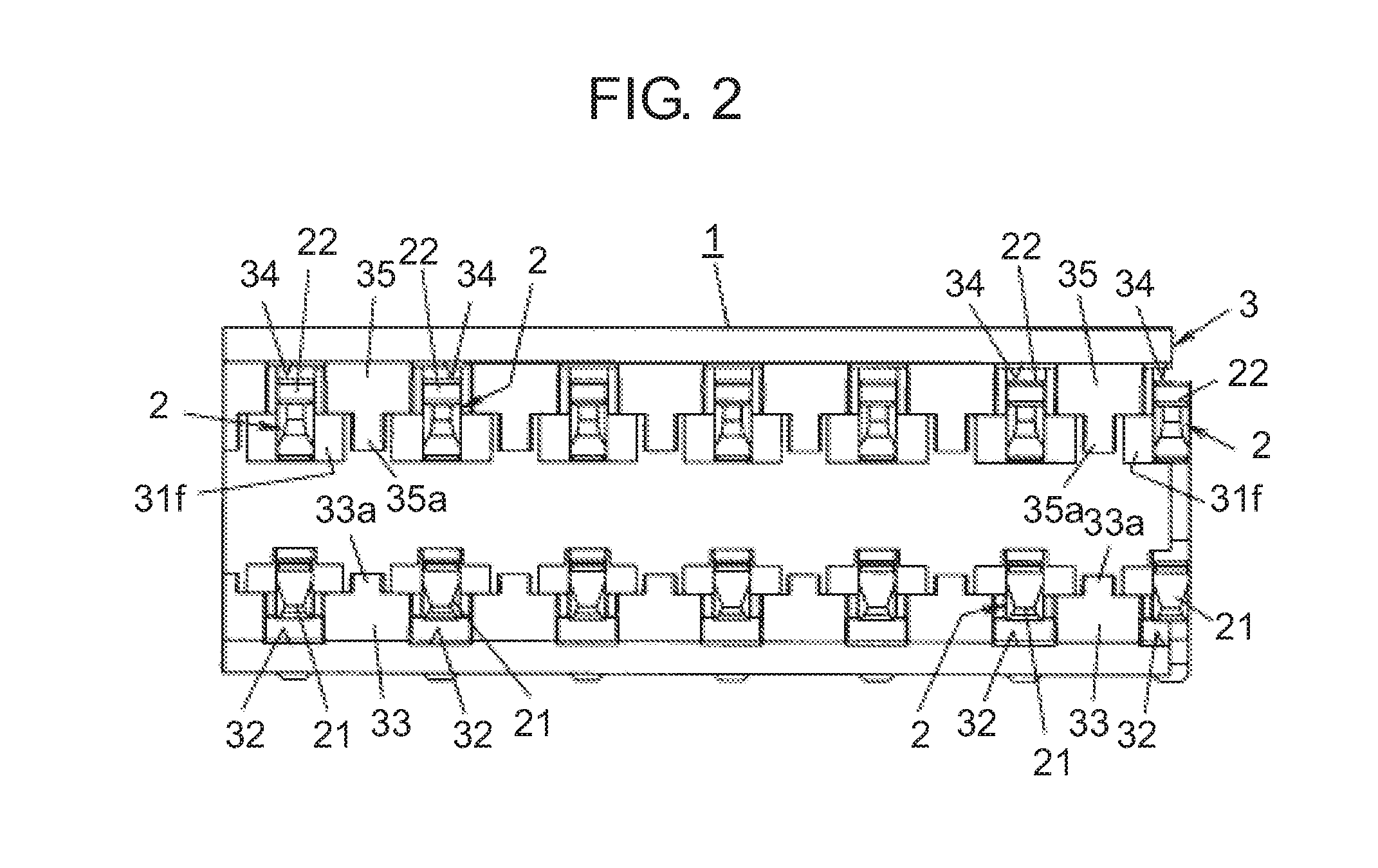
[0032]A connector according to the present exemplary embodiment is a substrate to FPC (Flexible Printed Circuits) connector, or a substrate to FFC (Flexible Flat Cable) connector. In the following, a description will be given of an exemplary embodiment of the connector with reference to FIGS. 1 to 9. Note that, in the following description, unless otherwise specified, top-bottom, right-left directions are defined on the basis of the orientation in FIG. 2. Further, it is defined that the direction perpendicular to FIG. 2 is the front-rear direction (the near side is the front side). Accordingly, the left side in FIG. 3A is the front side, and the right side in FIG. 3A is the rear side.

[0033]Connector 1 according to the present exemplary embodiment is mounted on a substrate, and as shown in FIG. 5B, connector 1 is used for electrically connecting between FPC 100 being a plate-shaped connection target (target to be connected) and the substrate. FPC 100 includes flexible substrate 101, a p


PUM


Abstract

Housing includes: insertion part into which a connection target is inserted; a plurality of first grooves provided inside insertion part so as to align along an alignment direction being perpendicular to the insertion direction of the connection target, first contact parts being respectively disposed in first grooves; a plurality of second grooves provided inside insertion part so as to oppose to first grooves, second contact parts being respectively disposed in second grooves first partition wall partitioning adjacent first contact parts; and second partition wall partitioning adjacent second contact parts. At least one of first partition wall and second partition wall has a height dimension in a direction perpendicular to both the insertion direction and the alignment direction, the height dimension being smaller at least at one end in the alignment direction than at a portion between opposite ends in the alignment direction.

Description


Claims


Application Information

Patent Timeline
Owner PANASONIC INTELLECTUAL PROPERTY MANAGEMENT CO LTD
Why Eureka
Try Eureka