Indoor positioning and communications system

a communication system and positioning technology, applied in the field of people and/or objects, can solve the problems that the global positioning system often does not function inside the building, and the frequency at which gps signals operate does not typically permit transmission, so as to increase the range of an area, increase the degree of accuracy, and extend the range of a beacon

Active Publication Date: 2017-07-27
LIVESENTINEL INC
View PDF0 Cites 0 Cited by
  • Summary
  • Abstract
  • Description
  • Claims
  • Application Information

AI Technical Summary

Benefits of technology

This patented technology allows location sensing systems like PHS® smartphones to detect if someone falls down during their stay inside a specific space such as a house or office. They use signals called LSPRs - Time Of Flight Protocols to transmit data between them and receive feedback about who they were near based upon factors like altitude. By measuring these distances, the technologies allow users to locate assets nearby without having to manually check around every room. Additionally, the technology includes wireless communication networks used to send notifications wirelessly to servers attached to buildings. Overall, this technology improves efficiency and precision in locating individuals while minimizing human effort required.

Problems solved by technology

The technical problem addressed by this patented technology is how to create an affordable way to locate individuals within buildings without having any obstructions like cables or wires from outside their walls when they are needed.

Method used


Image

  • Indoor positioning and communications system
  • Indoor positioning and communications system
  • Indoor positioning and communications system

Examples


Embodiment Construction

[0020]Technologies need to be implemented in order to be able to position people or objects inside a building. As the population continues to age, people are living longer and are more likely to develop dementia or related debilitating diseases. Therefore, the features of the inventive concepts may be useful in positioning patients.

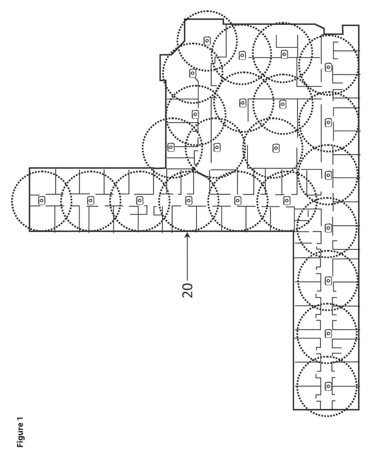
[0021]For example, shown in FIG. 1, an indoor positioning and communication system in accordance with some embodiments may broadcast a signal or beacon 20 throughout a facility regardless of location in the facility of a wearer of a receiver of the beacon 20. Each circle 20 in FIG. 1 may refer to a beam output by a position beacon device 110 alone or in combination with a satellite beacon device 120, for example, a 15 radius. Thus a position beacon device 110 may be 30 feet or so from a neighboring beacon device or satellite beacon device 120. The wearer may be placed, or positioned, in a particular room of the facility, for example, a long term care facilit


PUM


Abstract

The inventive concepts provides indoor positioning capabilities and door monitoring to facilities including but not limiting to day care providers and elderly care facilities in order for them to be able to quickly position someone inside the building as well as to be forewarned when they are going somewhere they shouldn't be i.e. near an exit way. The system also offers two way communications to the staff in the facility when a management server is implemented.

Description


Claims


Application Information

Patent Timeline
Owner LIVESENTINEL INC
Why Eureka
Try Eureka