Container Storage Facility

a container and storage technology, applied in the direction of conveyor parts, transportation and packaging, electric devices, etc., can solve the problems of deterioration of the substrates in the containers, the inability to supply inert gas to the containers stored in the storage sections, and the inability to retrieve or take out containers from storage sections, so as to reduce the likelihood of deterioration of the one or more substrates in the container, the effect of reducing the likelihood of deterioration of the one or more substra

Active Publication Date: 2018-03-15
DAIFUKU CO LTD
View PDF2 Cites 3 Cited by
  • Summary
  • Abstract
  • Description
  • Claims
  • Application Information

AI Technical Summary

Benefits of technology

The technical effect of this patented design is that even if there are problems with the container's ability to function properly due to factors like damage caused during normal operation, inert gases can help maintain their proper performance. This reduces the risk of failure in other parts of the container.

Problems solved by technology

The technical problem addressed in this patent is how to efficiently provide inert gas to a container storage facility without requiring expensive equipment like redundant gas suppliers or electrically insulated gateways.

Method used


Image

  • Container Storage Facility
  • Container Storage Facility
  • Container Storage Facility

Examples


Embodiment Construction

[0023]Embodiments of a container storage facility are described next with reference to the drawings.

[0024]As shown in FIGS. 3 and 4, the container storage facility of the present embodiment includes two container storage structures J (a first container storage structure J1 and a second container storage structure J2), a first controller Hs, a second controller Hp, and a managing device H.

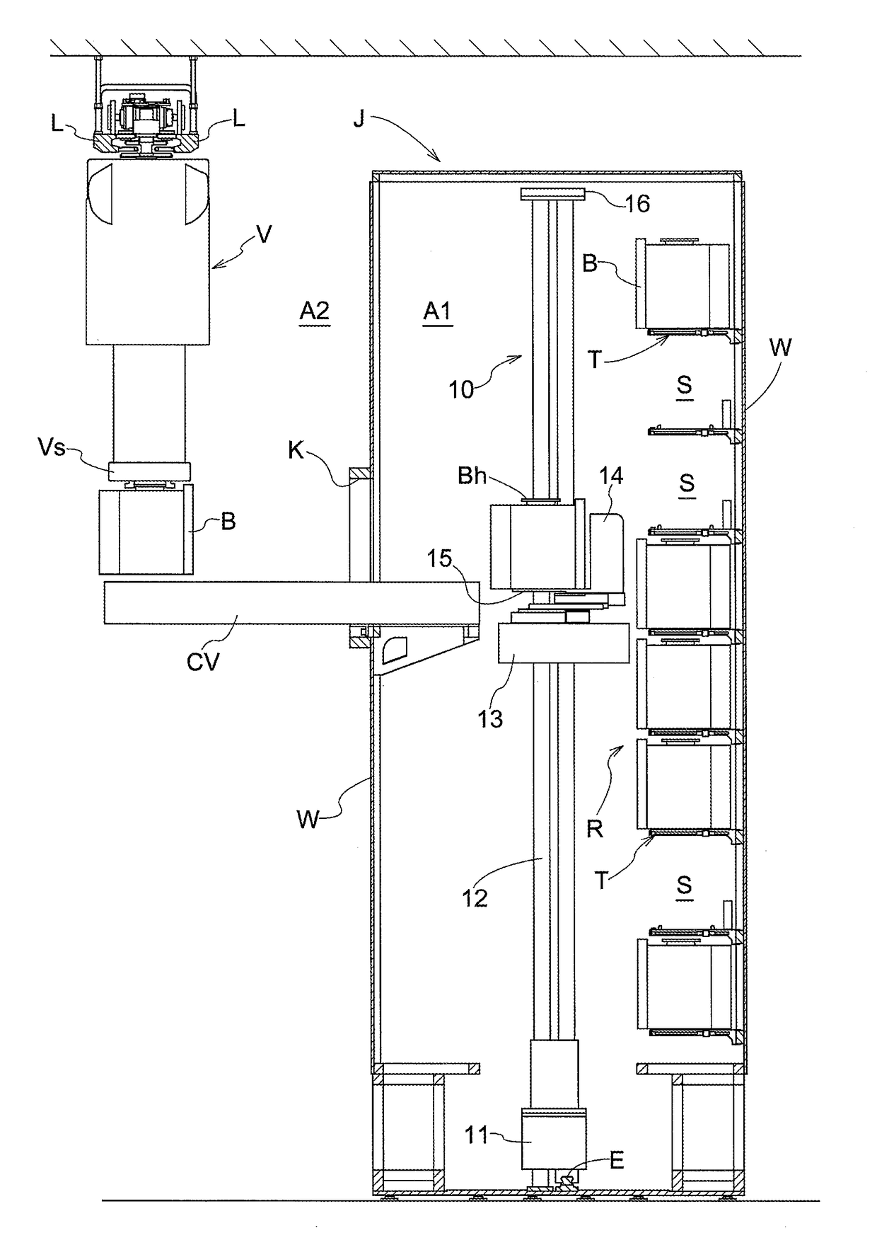
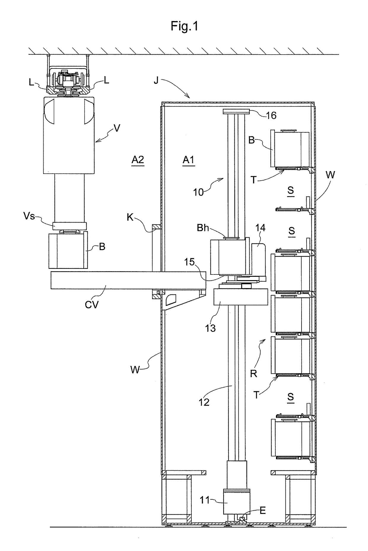
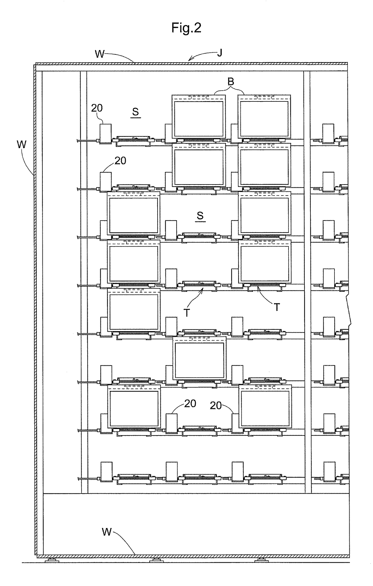
[0025]As shown in FIGS. 1 and 2, each container storage structure J includes a storage rack R configured to store containers B each configured to hold one or more substrates under a sealed condition, a stacker crane 10 which functions as a transporting device configured to transport the containers B, one container B at a time, and one or more carry-in-and-out conveyors CV which function as carry in and out portions for the containers B. As shown in FIGS. 3 and 4, in the present embodiment, two container storage structures J (first container storage structure J1 and second container storage structure J2


PUM


Abstract

A facility comprises an inactive gas supplying device configured to supply inert gas to a container, a transport device configured to carry a container into, and out of, a storage section, a first controller configured to control the transport device, a second controller configured to control the inactive gas supplying device, and a third controller configured to transmit a first command to the first controller through a communications relay device, and to transmit a second command to the second controller Hp. The transport device receives electric power from the first electric power supply whereas the inactive gas supplying device, the second controller, the third controller, and the communications relay device receive electric power from one or more different-path electric power supplies each of which is different from the first electric power supply.

Description


Claims


Application Information

Patent Timeline
Owner DAIFUKU CO LTD
Why Eureka
Try Eureka