Apparatus and method for checking whether table is at tilt
a technology of tilting and apparatus, applied in the field of apparatus and method for checking whether the table is tilting, can solve problems such as reducing yield, and achieve the effect of enhancing yield and enhancing inspection accuracy
- Summary
- Abstract
- Description
- Claims
- Application Information
AI Technical Summary
Benefits of technology
Problems solved by technology
Method used
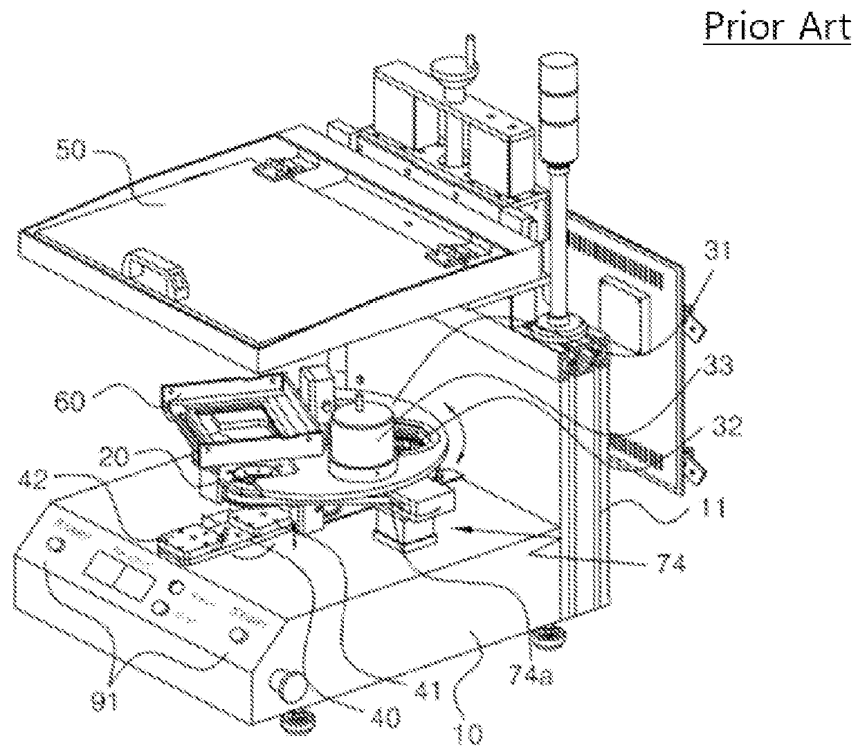
Image

Examples
first embodiment
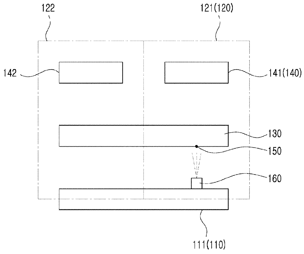
[0042]FIG. 3 is a schematic view of a table tilt checking apparatus according to the present disclosure.
[0043]A table tilt checking apparatus according to a first embodiment of the present disclosure may be adopted for use in a camera module inspecting apparatus, and may include a first position mark 150 and a first mark photographer 160, as illustrated in FIG. 3.
[0044]As illustrated in FIG. 3, the camera module inspecting apparatus may include a fixing part 110, a plurality of test zones 120 provided above the fixing part 110, a moving table 130 to guide a camera module (not shown) sequentially to the respective test zones 120, and charts 140 respectively provided in one or more of a plurality of test zones 120. Further, one or more test zones 120 may include first and second test zones 121 and 122, and one or more charts 140 may include a first chart 141 provided in the first test zone 121 and a second chart 142 provided in the second test zone 122.
[0045]Accordingly, the camera modul
third embodiment
[0066]Accordingly, in the present disclosure, by installing only one expensive mark photographer 160 on one portion of the fixing part 110 that corresponds to the first test zone among a plurality of test zones 121, 122 where an item in most need of the tilt inspection is positioned, and installing relatively cheaper position marks 150, 250 on respective portions of the table 130 all across the test zones 121, 122, cost can be reduced, and more accurate tilt checking is enabled through a plurality of portions of the table 130.
[0067]Hereinbelow, a table tilt checking apparatus according to a fourth embodiment of the present disclosure will be described with reference to FIG. 6. FIG. 6 is a schematic view of a table tilt checking apparatus according to a fourth embodiment of the present disclosure.
[0068]As illustrated in FIG. 6, the table tilt checking apparatus according to the fourth embodiment of the present disclosure is almost identical to that according to the first embodiment of t
sixth embodiment
[0079]Accordingly, in the present disclosure, by installing only one expensive mark photographer 360 on one portion of the first pillar part 312 that corresponds to the first test zone among a plurality of test zones 121, 122 where an item in most need of the tilt inspection is positioned, and installing relatively cheaper position marks 350, 450 on respective portions of the table 330 all across the test zones 121, 122, cost can be reduced, and more accurate tilt checking is enabled through a plurality of portions of the table 330.
[0080]Hereinbelow, a table tilt checking apparatus according to a seventh embodiment of the present disclosure will be described with reference to FIG. 9. FIG. 9 is a schematic view of a table tilt checking apparatus according to a seventh embodiment of the present disclosure.
[0081]As illustrated in FIG. 9, the table tilt checking apparatus according to the seventh embodiment of the present disclosure is almost identical to the first embodiment of the presen
PUM
 Abstract
Description
Claims
Application Information
 - R&D Engineer
- R&D Manager
- IP Professional
- Industry Leading Data Capabilities
- Powerful AI technology
- Patent DNA Extraction
Browse by: Latest US Patents, China's latest patents, Technical Efficacy Thesaurus, Application Domain, Technology Topic.
© 2024 PatSnap. All rights reserved.Legal|Privacy policy|Modern Slavery Act Transparency Statement|Sitemap