Electronic Pressure Switch

Inactive Publication Date: 2018-12-27
COELBO CONTROL SYST
View PDF5 Cites 3 Cited by
  • Summary
  • Abstract
  • Description
  • Claims
  • Application Information

AI Technical Summary

Benefits of technology

Problems solved by technology

The technical problem addressed in this patent is how to improve the functionality of a pressure switch in a simplified manner.

Method used


Image

  • Electronic Pressure Switch
  • Electronic Pressure Switch
  • Electronic Pressure Switch

Examples


Embodiment Construction

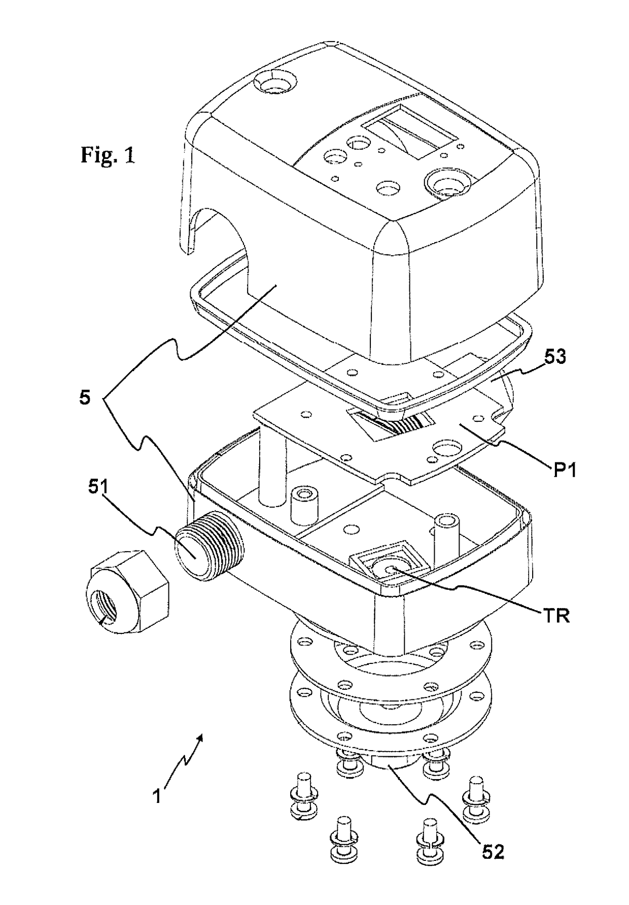
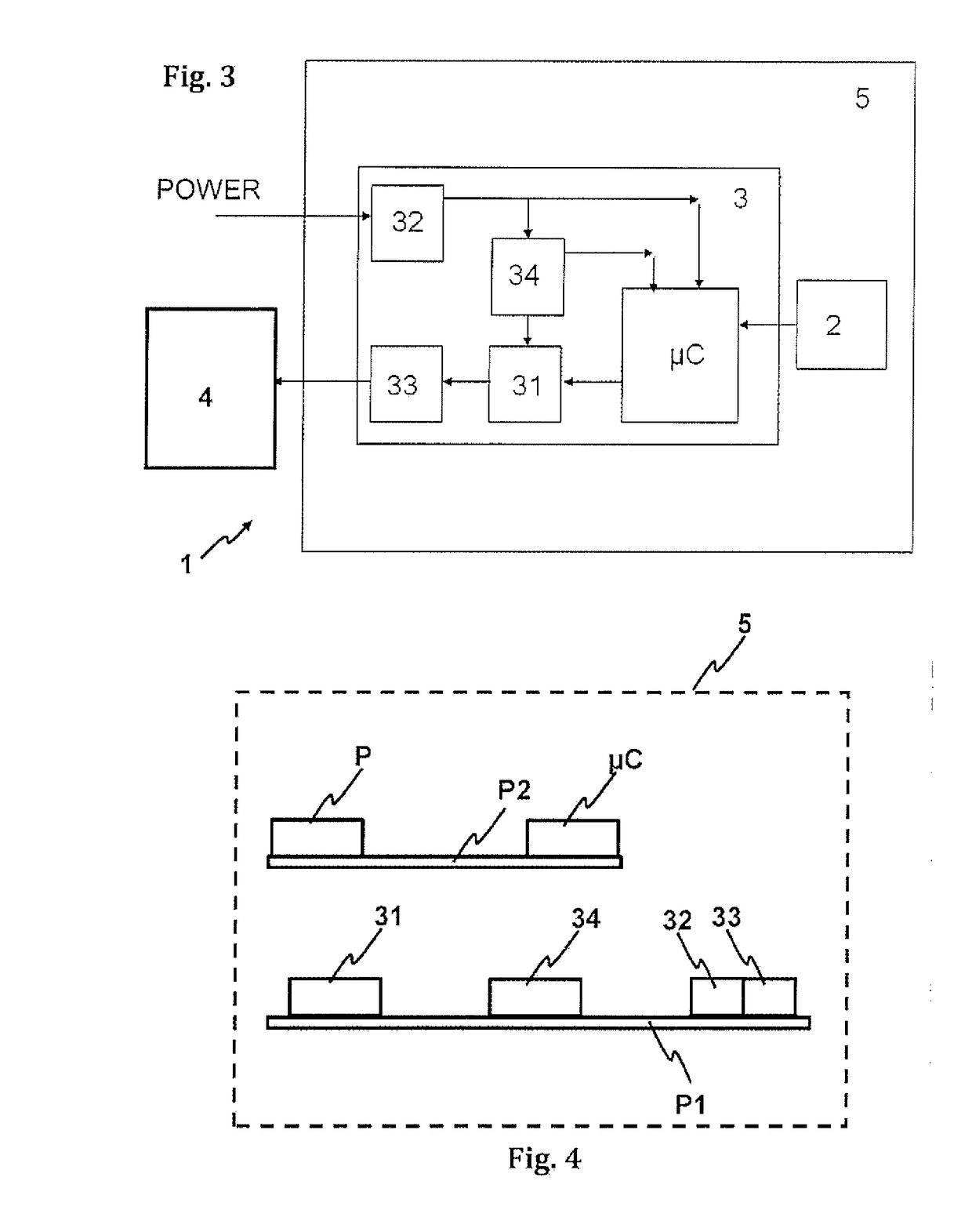
[0019]To overcome the above drawbacks, the present invention proposes an electronic pressure switch comprising:[0020]a protective housing[0021]a pressure sensor;[0022]a circuit provided with:[0023]a switch for activation / deactivation of an electric pump,[0024]terminals for connection between the pressure switch and the electric pump,[0025]a power supply terminal,[0026]a microcontroller for controlling the switch, which receives signals from the pressure sensor,

[0027]wherein the electrical circuit comprises a current sensor connected to the microcontroller, and wherein the pressure sensor, the electrical circuit and the microcontroller are arranged on the inside of the protective housing, so that it constitutes an electronic pressure switch with autonomous protection functions.

[0028]Thanks to the inclusion of the current sensor and the microcontroller, the pressure switch can extend its normal functions by adding the circuit breaking function of the electric pump due to overcurrent, s


PUM


Abstract

Electronic pressure switch comprising a pressure sensor and a circuit provided in turn with a switch for the activation/deactivation of an electric pump, an input terminal and an output terminal for connection to the mains and connection between the pressure switch and the electric pump and a microcontroller for controlling the switch, which receives signals from the pressure sensor, wherein the electric circuit comprises a current sensor connected to the microcontroller, so that it can stop the operation of the electric pump due to overcurrent, thus avoiding having to mount a specific sensor in the electric pump. It also allows, by interacting with the pressure sensor through a programmed logic, an operation of the electric pump in no-load condition, without water, as well as water hammers, to be detected with greater reliability.

Description


Claims


Application Information

Patent Timeline
Owner COELBO CONTROL SYST
Why Eureka
Try Eureka