Image projection system and correction method

a projection system and image technology, applied in the field of image projection system, can solve the problems of high cost, inability to use a general-purpose smartphone, and restricted functions of portable information terminals, and achieve the effect of large-scale and high cos

Active Publication Date: 2019-03-21
SONY CORP
View PDF0 Cites 7 Cited by
  • Summary
  • Abstract
  • Description
  • Claims
  • Application Information

AI Technical Summary

Benefits of technology

The technical effect in this patented technology allows users with specialized devices like tablets or phones can access their location data without being limited due to limitations on how they are able to communicate wirelessly. This makes them more accessible than regular computers while also allowing these devices to be used indoors where signal strengths may vary widely from one area to another. Additionally, there're some ways to detect geographic locations accurately even when no device has been connected to communication networks such as WiFi.

Problems solved by technology

The technical problem addressed in this patented text relates to how to improve the quality of images displayed on screens by reducing any deformation caused when they are viewed from different angles or perspectives relative to their normal direction.

Method used


Image

  • Image projection system and correction method
  • Image projection system and correction method
  • Image projection system and correction method

Examples


embodiments

[Configuration]

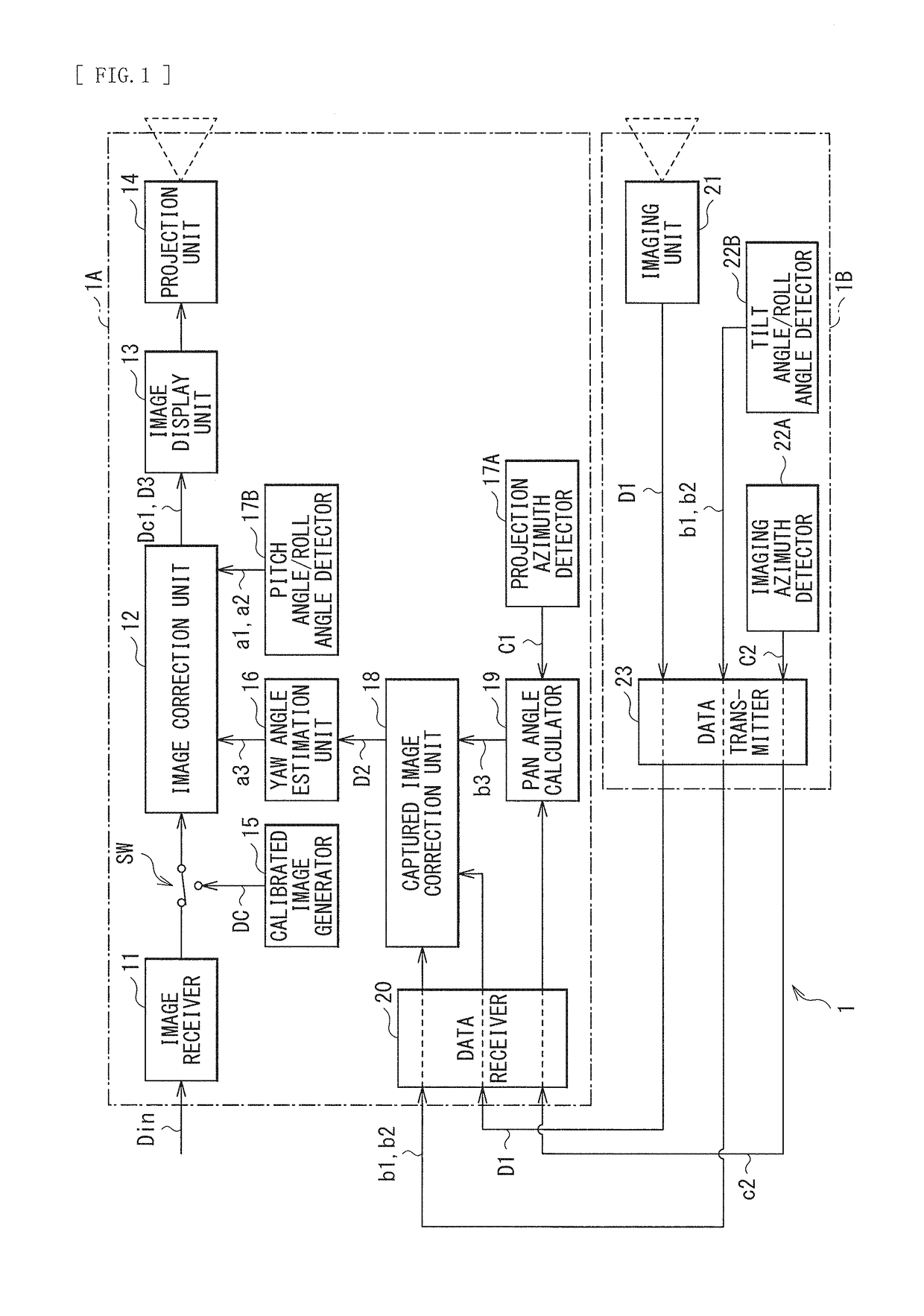
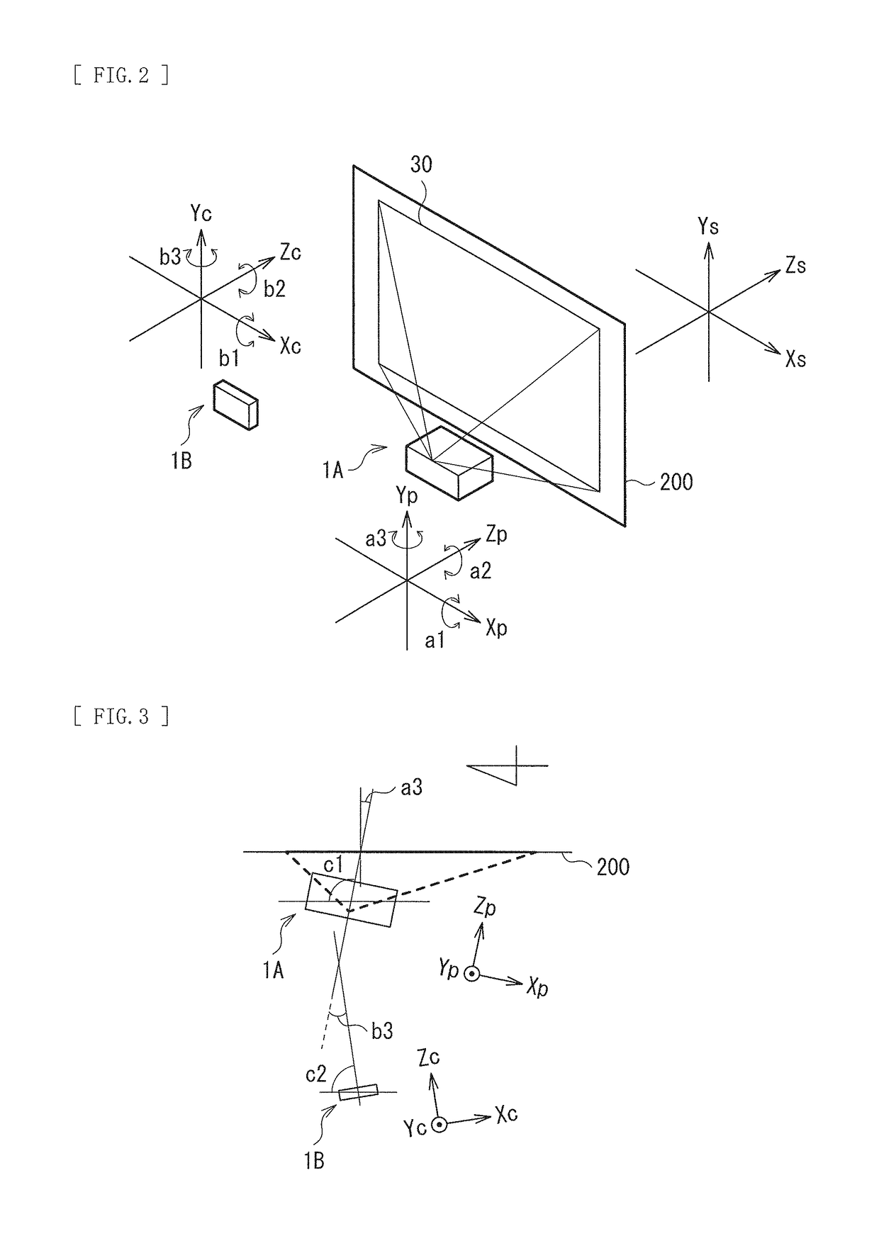
[0029]FIG. 1 is a diagram of a configuration of an image projection system (image projection system 1) including an image projection system (image projection system 1) according to an embodiment of the disclosure. The image projection system 1 includes a projector 1A and a portable terminal 1B. FIG. 2 is an explanatory diagram of a rotation angle in the projector 1A and the portable terminal 1B. FIG. 3 is an explanatory diagram of an azimuth of each optical axis of the projector 1A and the portable terminal 1B.

[0030]First, with reference to FIG. 2, an orthogonal coordinate system and an inclination (rotation angle) of the projector 1A and the portable terminal 1B are described. An orthogonal coordinate system Xs-Ys-Zs is a static coordinate system based on a direction of gravitational force and a screen 200. Here, by way of example, an Xs axis is a horizontal direction, and a Ys axis is a vertical direction. A projection plane (projection plane 30) of the screen 200 is a


PUM


Abstract

The image projection system includes a projection-type display apparatus that projects an image onto a projection plane and has a first azimuth detector, the first azimuth detector detecting a projection azimuth; an imaging apparatus that images a projection screen of the image and has a second azimuth detector, the second azimuth detector detecting an imaging azimuth; and a signal processor that performs correction processing of the image. The signal processor includes an estimation unit and a correction unit, the estimation unit estimating an inclination of the projection-type display apparatus to the projection plane on the basis of the projection azimuth detected by the first azimuth detector, the imaging azimuth detected by the second azimuth detector, and the captured image acquired by the imaging apparatus; and the correction unit correcting a shape of the projection screen on the basis of the inclination of the projection-type display apparatus estimated by the estimation unit.

Description


Claims


Application Information

Patent Timeline
Owner SONY CORP
Why Eureka
Try Eureka