Seat support mechanism

a seat and support mechanism technology, applied in the direction of seats, movable seats, chairs, etc., can solve the problems of increasing the cost of parts, increasing the difficulty of discharging parts in a limited space around the legs of seats, and increasing the change-over time, so as to reduce the cost, improve the operability, and simplify the structure

Active Publication Date: 2019-08-08
KOITO ELECTRIC IND
View PDF12 Cites 0 Cited by
  • Summary
  • Abstract
  • Description
  • Claims
  • Application Information

AI Technical Summary

Benefits of technology

The inventive chair supporting system has several technical features: It uses an easy-to-use linkage between its backrests and arm supports instead of just having one thing fixed together like this traditional method used with chairs or bicycles. This makes them easier to move about without getting stuck during use. Additionally, there are fewer parts needed than previous designs which saves money while also improving their overall appearance. Overall, these improvements improve comfort level and reduce costs associated with sitting furniture.

Problems solved by technology

The technical problem addressed in this patented text relates how to efficiently switch both sides of an automobile's seat into different directions without causing any gaps where pausing spaces occur due to installation issues like installing rails near walls during construction work hours.

Method used


Image

  • Seat support mechanism
  • Seat support mechanism
  • Seat support mechanism

Examples


Embodiment Construction

[0069]Hereinbelow, an embodiment representing the present invention will be explained with reference to the drawings.

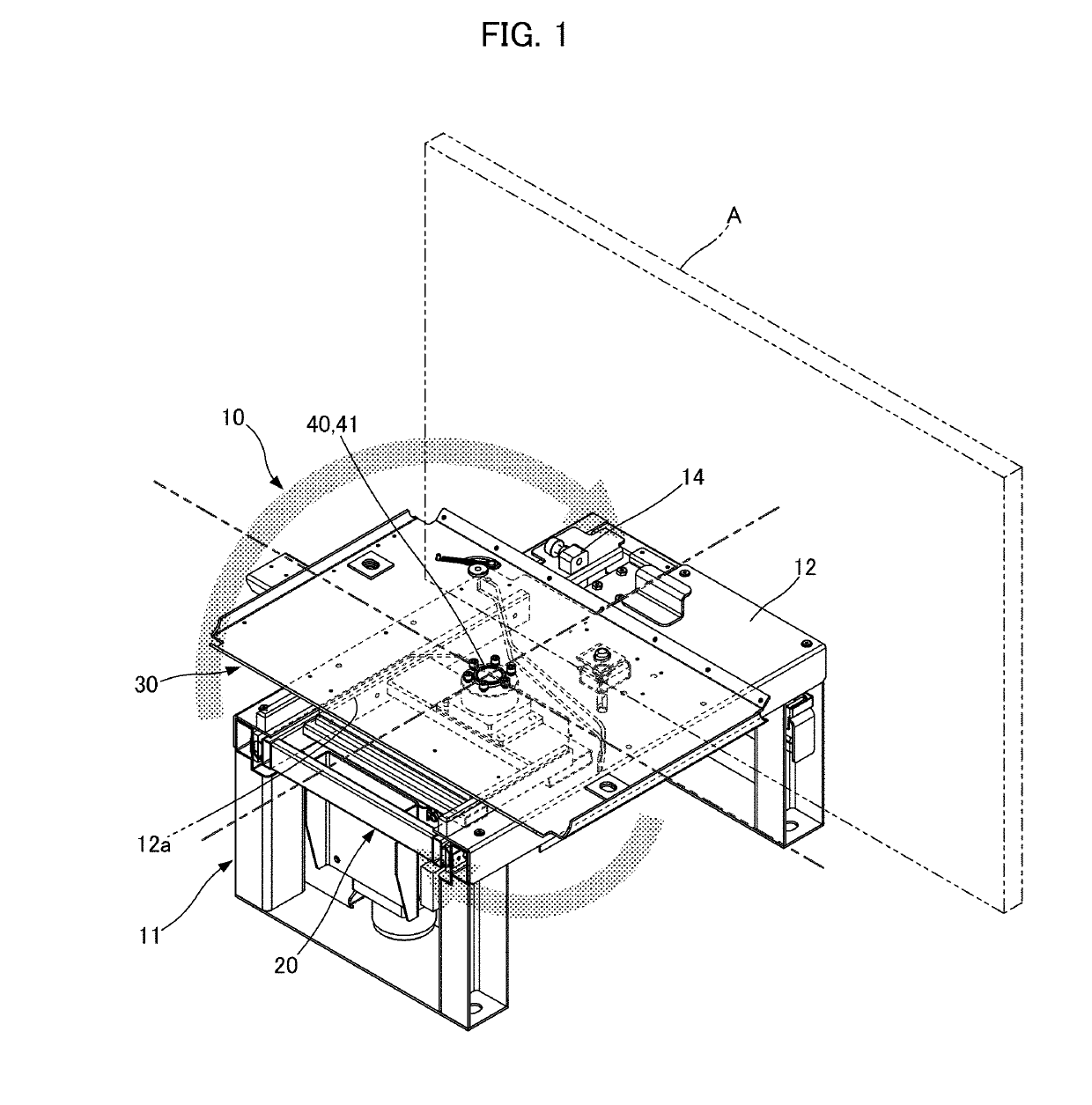
[0070]FIG. 1 to FIG. 26 show one embodiment of the present invention.

[0071]A seat support mechanism 10 according to an embodiment of the present invention is for turning a seat to change over the directed state thereof. Herein, the application for the seat is not particularly limited, however, hereinbelow, the case where the present invention is applied to a bench for two occupants that is to be equipped in a cabin of a railroad vehicle will be explained as an example. The symbol “A” in FIG. 1 denotes a part of a wall face in the vehicle cabin. Herein, the wall face refers to an internal wall face of a side wall provided in parallel with the direction of travel of the vehicle, and hereinbelow it will be referred to as the side wall A.

[0072]As shown in FIG. 1, the seat support mechanism 10 includes a leg pedestal 11, a moving pedestal 20, and an underframe 30 of the seat.


PUM


Abstract

A seat support mechanism including a leg pedestal (11), which is fixedly provided on a floor in the vicinity of a side wall (A), a moving pedestal (20), which is disposed under a top face part (12) of the leg pedestal (11) and is capable of being advanced/retracted in a direction orthogonal to the side wall A; an underframe (30) of the seat, which is disposed above the top face part (12) of the leg pedestal (11), and is turnably supported by a turning shaft (41) in the moving pedestal (20), the turning shaft (41) avoiding an interference with the top face part (12), and an interlocking mechanism (50), which interlocks turning and advancing/retracting of the underframe (30), in which, when the seat is turned together with the underframe (30), the interlocking mechanism (50) converts the turning motion of the underframe (30) into a linear motion and, through the turning shaft (41), transmits it to the moving pedestal (20), thereby causing the moving pedestal (20) and the underframe (30) to be advanced/retracted in a direction orthogonal to the side wall (A).

Description


Claims


Application Information

Patent Timeline
Owner KOITO ELECTRIC IND
Why Eureka
Try Eureka