Image processing device and image processing method

Active Publication Date: 2019-10-10
SONY CORP
View PDF0 Cites 3 Cited by
  • Summary
  • Abstract
  • Description
  • Claims
  • Application Information

AI Technical Summary

Benefits of technology

[0012]As described above, according to the present disclosure, it is possible to extract a target region for a far-infrared image with a high level of accuracy.
[0013]Note that the effects described above are

Problems solved by technology

However, in such a method, the amount of data used in each processing may become relatively large, and thus the consumption of a memory may increase as compared to a method using shutter correction.
Therefore, the extraction of the arm region as a target region is not appropriately performed.
In this manner, in the far-infrared image, it may become difficult to extract a target region with a high level of accuracy due to a fluctuation in a pixel value which may occur due to a fluctuation in the temperature of the imaging element caused by incidence of infrared energy from a portion other than a subject.
Therefore, the speed of an increase in a pixel value after shutt

Method used


Image

  • Image processing device and image processing method
  • Image processing device and image processing method
  • Image processing device and image processing method

Examples


Example

[0032]3. Modification example

3-1. Outline of inter-frame differencing technique

3-2. Functional configuration

3-3. Operation

4. Summary

1. INTRODUCTION

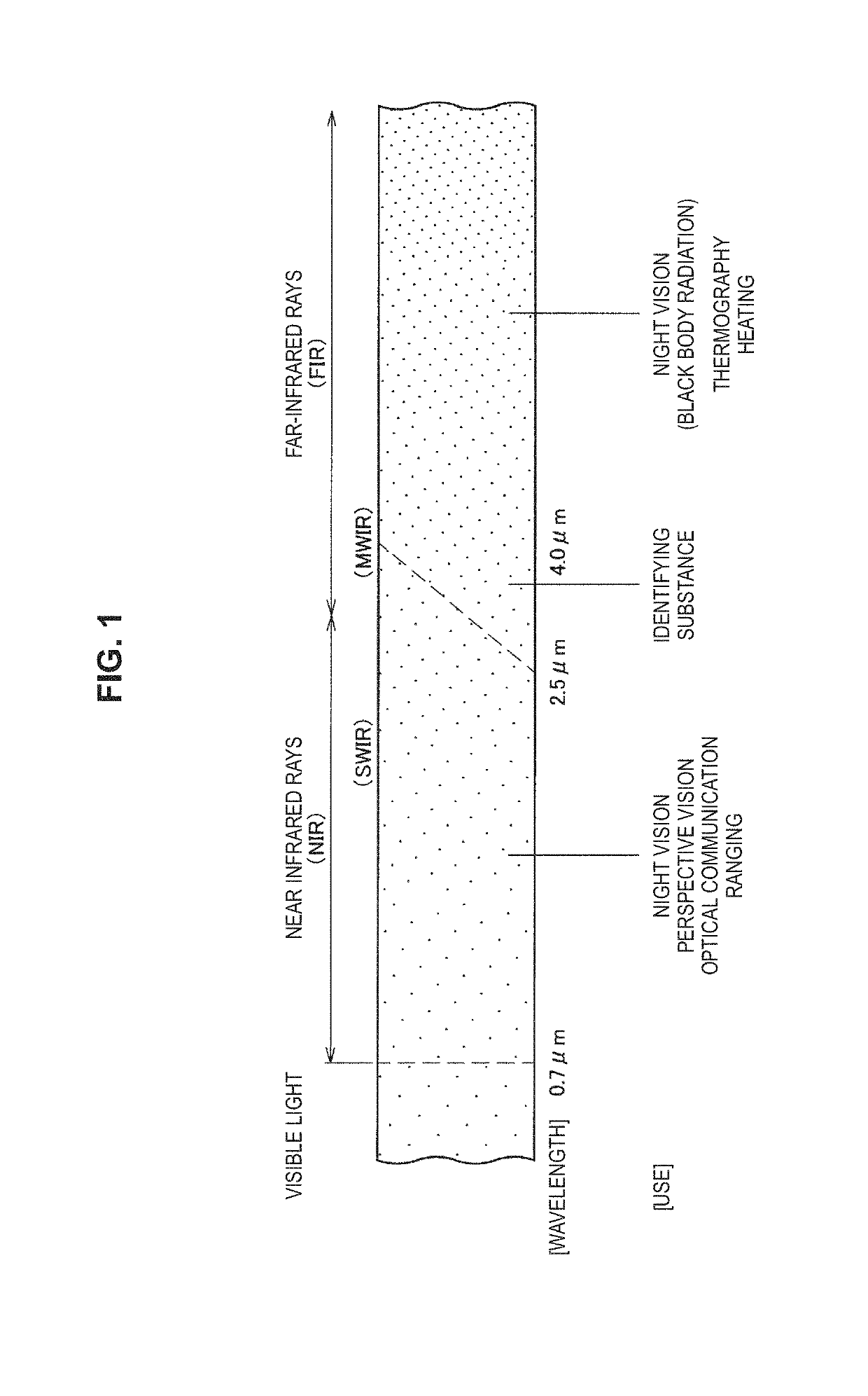
[0033]FIG. 1 is an explanatory diagram illustrating various applications of an infrared image which depends on a wavelength. The horizontal direction of FIG. 1 corresponds to a wavelength of the infrared light and the wavelength is lengthened from the left to the right. Light that has a wavelength equal to or less than 0.7 μm is visible light and a human visual sense detects the visible light. A wavelength region adjacent to the visible light region is a near-infrared light region (NIR) and the infrared light belonging to the NIR region is referred to as near-infrared light. The upper limit of the wavelength of the NIR region differs depending on definition and is between 2.5 μm to 4.0 μm in many cases. A portion with a relatively long wavelength in the NIR region is also referred to as a short-wavelength infrared (SWIR) region in some cases


PUM


Abstract

[Object] To extract a target region for a far-infrared image with a high level of accuracy.
[Solution] Provided is an image processing device including: an adjustment unit that adjusts any one of a background image which is a far-infrared image showing a background that does not include an object and a target image which is a far-infrared image showing the object, on the basis of a time change model of an observation pixel value; and an extraction unit that extracts a target region including the object in the target image on the basis of a result of comparison between the background image and the target image after the adjustment is performed.

Description


Claims


Application Information

Patent Timeline
Owner SONY CORP
Why Eureka
Try Eureka