Transformer for a dc/dc voltage converter

Pending Publication Date: 2020-04-30
SIEMENS AG
View PDF0 Cites 0 Cited by
  • Summary
  • Abstract
  • Description
  • Claims
  • Application Information

AI Technical Summary

Benefits of technology

[0014]The capacitor arrangement and the transformer unit form a structural unit in which the capacitor arrangement is virtually integrated into the transformer unit. This makes it possible to use, for example, flat parts or wires, or stranded wires to create a required electrical connection. The electrical connections are thereby able to be configured so as to be short, which is advantageous, for example, at high transmission frequencies, as the losses arising due to the skin and proximity effect are able to be kept small It is additionally thereby made possible to use structurally smaller ceramic capacitors. Since the capacitor arrangement together with the transformer unit forms a structural unit, it is possible to arrange

Problems solved by technology

One disadvantage of this procedure is that it results in a hi

Method used


Image

  • Transformer for a dc/dc voltage converter
  • Transformer for a dc/dc voltage converter
  • Transformer for a dc/dc voltage converter

Examples


Embodiment Construction

[0031]In the present description, same elements are provided with same reference signs.

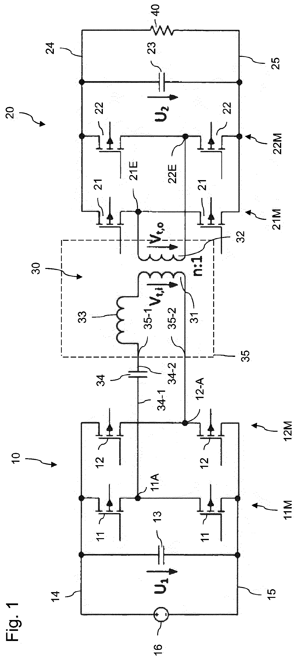
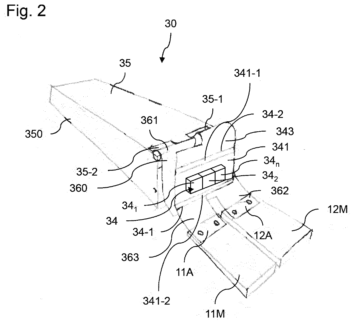
[0032]A transformer configured according to an embodiment, as shown schematically by way of example in a perspective illustration in FIG. 2, is used, for example, in a series resonant converter, as shown in FIG. 1. The transformer 30 according to one or more of the present embodiments includes a transformer unit 35 that includes the primary coil 31 already described in the introduction. The transformer unit 35, in addition to the primary winding 31, includes the secondary winding 32 and a stray inductance 33 that occurs during operation. It is therefore assumed in the following description that the stray inductance 33 is a component of the primary winding 31.

[0033]The transformer unit 35 is arranged in a housing 350 that has a substantially cuboid structure, merely by way of example. For the further description of the present embodiments, only the connection of the primary winding 31 to the first bri


PUM


Abstract

A transformer for a DC-DC converter, such as a resonant converter, is provided. The converter includes a transformer unit that includes at least one winding with a first winding connection and a second winding connection, and a capacitor assembly consisting of at least one capacitor with a first capacitor assembly connection and a second capacitor assembly connection. The capacitor assembly is arranged so as to lie against the transformer unit in order to form an assembly. The capacitor assembly connections are connected to the winding connections via one or more first connection parts in a specified manner with respect to the electric connections. The capacitor assembly connections and/or the winding connections are electrically connected to multiple second connection parts in a specified manner with respect to the electric connections for connecting to a first power module and a second power module.

Description


Claims


Application Information

Patent Timeline
Owner SIEMENS AG
Why Eureka
Try Eureka