Separation system

a separation system and hydrogen technology, applied in the direction of electrical generators, energy-based chemical/physical/physical-chemical processes, chemistry apparatus and processes, etc., can solve the problems of less enticing, hindering the possibility of sustaining the production rate of h2 necessary for automotive and industrial applications, and even more critical production of nox during combustion process, so as to reduce the thickness of hydrogen separation membranes, reduce costs, and increase the hydrogen production rate

Active Publication Date: 2020-12-10
GALBIATI CRISTIANO
View PDF0 Cites 3 Cited by
  • Summary
  • Abstract
  • Description
  • Claims
  • Application Information

AI Technical Summary

Benefits of technology

The technical effect of this patented technology is that it allows for efficient separating of gas mixtures containing two types of molecules (hydrogen) without requiring expensive equipment such as platinum electrodes. It also increases the efficiency of producing high purity hydrogen while maintaining cost reduction. Additionally, there are various ways to improve the performance of these devices.

Problems solved by technology

This patent describes various technical problem addressed in this patent text relating to the development of an improved apparatus for generating ammonia from ammonia sources like urea, ammonia, and ammonia hydride. Existing methods involve expensive equipment and processes, making them difficult to implement in practicality.

Method used


Image

  • Separation system
  • Separation system

Examples


Embodiment Construction

[0040]While the invention is susceptible to various modifications and alternative constructions, some of the illustrated embodiments are shown in the drawings and will be described below in detail.

[0041]It must be understood, however, that there is no intention to limit the invention to the specific illustrated embodiments, but, on the contrary, the invention intends to cover all the modifications, alternative constructions and equivalents that fall within the scope of the invention as defined in the claims.

[0042]The use of “such as”, “etc.”, “or” indicates non-exclusive alternatives without limitations, unless otherwise indicated.

[0043]The use of “includes” means “includes, but is not limited to”, unless otherwise indicated.

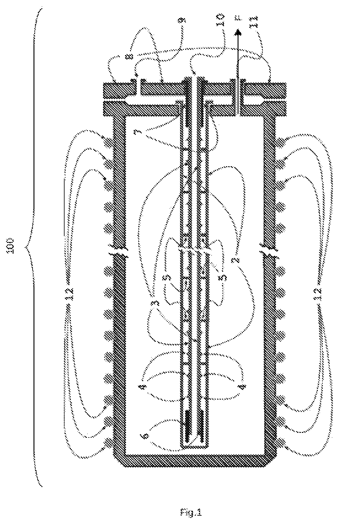
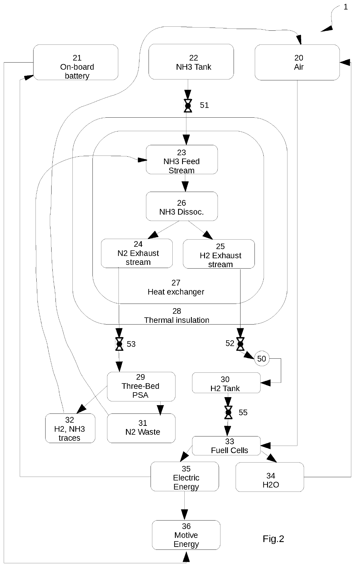
[0044]FIG. 1 illustrates a preferred embodiment of the innovative separation system for hydrogen production.

[0045]The main containment vessel or hydrogen exhaust chamber 100 of the separation system 1 is preferably made of stainless steel or other heat resistant me


PUM


Abstract

(EN) The present invention relates to the field of high efficiency and high flow hydrogen generation and purification from a hydrogen tank provided in the form of ammonia (NH3). In particular, the present invention describes in particular an innovative and compact system for the dissociation of ammonia and therefore the production of molecular hydrogen (H2), all in a cycle totally free of carbon (hence carbon emissions), as well as by the generation of nitrogen oxide and nitric dioxide (NOx).

Description


Claims


Application Information

Patent Timeline
Owner GALBIATI CRISTIANO
Why Eureka
Try Eureka