Fluorinated imide salt compound and surfactant
a technology of imide salt and fluorinated imide salt, which is applied in the directions of transportation and packaging, organic chemistry, mixing, etc., can solve the problems of high toxicity, high bioaccumulation, and restricted use of pfoa or pfos, and achieve excellent water stability and high surface tension reduction ability
- Summary
- Abstract
- Description
- Claims
- Application Information
AI Technical Summary
Benefits of technology
Problems solved by technology
Method used
Image


Examples
first embodiment
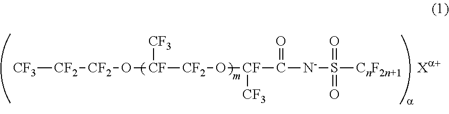
[0029]The fluorinated imide salt compound according to the first embodiment of the present invention is a compound represented by General Formula (2).
[0030]In General Formula (2), m represents 1 or 2, n represents an integer from 1 to 4, α represents 1 or 2, and Mα+ represents an α-valent metal ion, a primary ammonium ion, a secondary ammonium ion, a tertiary ammonium ion, or a quatemary ammonium ion.
[0031]The fluorinated imide salt compound represented by General Formula (2) has a structure in which m represents 1 or 2, and an oxyperfluoropropyl group is bonded to a carboxylic acid group of imide through an oxy perfluoropropylene group. Therefore, this compound has higher hydrophobicity and higher lipophobicity. In a case where m is 0, the hydrophobicity and lipophobicity are reduced, and the surface tension-reducing ability is lowered. Meanwhile, because the compound in which m is 3 or greater is difficult to synthesize, the synthesis cost increases.
[0032]The fluorinated imide salt c
second embodiment
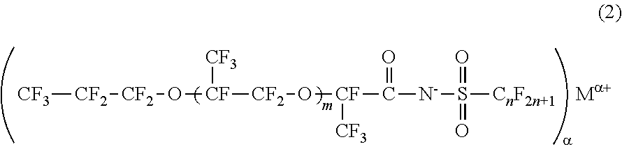
[0053]The fluorinated imide salt compound according to the second embodiment of the present invention is a compound represented by General Formula (3).
[0054]In General Formula (3), m represents 1 or 2, and n represents an integer from 1 to 4.
[0055]The structure of the fluorinated imide salt compound of the present embodiment is the same as the structure of the fluorinated imide salt compound of the first embodiment, except that the fluorinated imide salt compound of the first embodiment is a fluorinated imide ammonium salt compound in which α represents 1 and Mα+ represents an ammonium ion.
[0056]The fluorinated imide ammonium salt compound of the present embodiment can be manufactured, for example, by acidolyzing a fluorinated imide metal salt compound containing an α-valent metal ion as Mα+ by using sulfuric acid or hydrochloric acid so as to obtain a fluorinated imide compound containing a hydrogen atom as Mα+, and then neutralizing the obtained fluorinated imide compound with ammoni
example 1
of the Present Invention
[0066]A mixture (286.9 g) of CF3SO2NHK and KF and 425 mL of acetonitrile were put into a 4-neck glass flask equipped with a reflux condenser, a thermometer, and a stirrer, and stirred so that CF3SO2NHK was dissolved, thereby preparing a mixed solution containing dispersed KF. The mixture of CF3SO2NHK and KF was synthesized with reference to the method described in paragraph “0067” of Japanese Patent No. 5730513 by using trifluoromethanesulfonyl fluoride (CF3SO2F) instead of heptafluoropropanesulfonyl fluoride (C3F7SO2F).
[0067]Then, while being stirred, the prepared mixed solution was cooled with ice water, and 345.7 g of CF3CF2CF2OCF(CF3)CF2OCF(CF3)COF (CHEMINOX PO-3-AF, Unimatec Corporation.) was added dropwise to the mixed solution for 15 minutes. After the dropping ended, the ice water was removed, and the mixed solution was stirred at room temperature for 1 hour. Thereafter, the reaction solution was filtered, KF.HF precipitated during the reaction was separ
PUM
| Property | Measurement | Unit |
|---|---|---|
| Fraction | aaaaa | aaaaa |
| Surface energy | aaaaa | aaaaa |
| Surface energy | aaaaa | aaaaa |
Abstract
Description
Claims
Application Information
 - R&D Engineer
- R&D Manager
- IP Professional
- Industry Leading Data Capabilities
- Powerful AI technology
- Patent DNA Extraction
Browse by: Latest US Patents, China's latest patents, Technical Efficacy Thesaurus, Application Domain, Technology Topic.
© 2024 PatSnap. All rights reserved.Legal|Privacy policy|Modern Slavery Act Transparency Statement|Sitemap