Very-low-consumption reconfigurable-waveform compact UWB emitter
- Summary
- Abstract
- Description
- Claims
- Application Information
AI Technical Summary
Problems solved by technology
Method used
Image

Examples
first embodiment
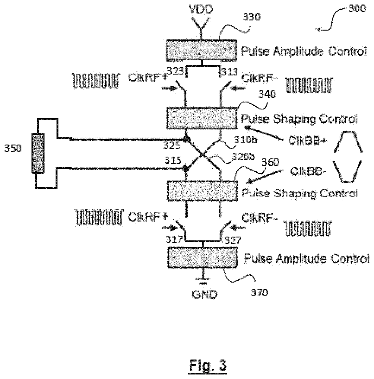
[0037]FIG. 3 schematically represents the general architecture of a UWB emitter, according to the invention.
[0038]The UWB emitter is based on an “H”-bridge, 300, comprising two branches in parallel. Like in the bridge of FIG. 2, we find in the first branch, a first switch 313, a midpoint 315 and a second switch 317. In the same way, we find in the second branch a first switch 323, a second midpoint 325 and a second switch 327. The first switch, 313, of the first branch, as well as the second switch of the second branch 327 are controlled by a first clock signal ClkRF−. The first switch, 323, of the second branch, as well as the second switch, 317, of the first branch are controlled by a second clock signal, ClkRF+ with a reverse polarity with respect to that of the first clock signal. The first and second clock signals have a frequency equal to the central frequency (RF frequency) of the UWB pulses to be generated.
[0039]The UWB antenna rising between the first midpoint 315 and the seco
second embodiment
[0104]FIG. 8 schematically represents the general architecture of a UWB emitter, according to the invention.
[0105]The amplitude control, power amplification and envelope shape control stages are identical to those of the first embodiment described in connection with FIG. 3. Hence, their description will not be repeated herein.
[0106]However, unlike the first embodiment, the UWB antenna, 850, is not fed in differential mode but is a single feed antenna. More specifically, the midpoint 815 of the first branch 810b, forming a first output of the emitter, is connected to a characteristic load of 50Ω, 855, via a decoupling capacitor, 853. The midpoint 825, of the second branch, 820b, forming a second output of the emitter is connected through a decoupling capacitor, 854, to the antenna 850. The capacitors 853 and 854 have identical values and are intended to impose no point of polarisation at the output of the emitter.
[0107]A person skilled in the art should understand that the different var
third embodiment
[0109]FIG. 9 schematically represents the general architecture of a UWB emitter according to the invention.
[0110]The third embodiment differs from the previous ones in that it comprises a plurality of H-bridges connected in parallel, the UWB pulses of each of the bridges being independently controlled and being combined at the terminals of a common UWB antenna through decoupling capacitors.
[0111]In this embodiment, the structure of the H-bridges may be in accordance with the first or the second embodiment, as described above.
[0112]For simplicity and without prejudice to generalisation, we will assume in the following that the structure of the bridges is in accordance with the first embodiment.
[0113]More specifically, the UWB emitter comprises a plurality N of H-bridges connected in parallel, 900, bearing the specific references TX PA1, . . . , TC PAN. The respective first midpoints, 915, of the first branches of each of these bridges are connected to a first common terminal 955 through
PUM
 Abstract
Description
Claims
Application Information
 - R&D Engineer
- R&D Manager
- IP Professional
- Industry Leading Data Capabilities
- Powerful AI technology
- Patent DNA Extraction
Browse by: Latest US Patents, China's latest patents, Technical Efficacy Thesaurus, Application Domain, Technology Topic.
© 2024 PatSnap. All rights reserved.Legal|Privacy policy|Modern Slavery Act Transparency Statement|Sitemap