Device and method for attaching a scale element or a protective tape therefor

a technology of protective tape and scale element, which is applied in the direction of measuring tapes, mechanical measuring arrangements, instruments, etc., can solve the problems of not being able to precisely align the scale support exactly with the measuring direction, long scales are needed for such position measurements, and being used in tape form for highly elastic scales

Inactive Publication Date: 2005-03-15
DR JOHANNES HEIDENHAIN GMBH
View PDF14 Cites 20 Cited by
  • Summary
  • Abstract
  • Description
  • Claims
  • Application Information

AI Technical Summary

Benefits of technology

The technical effect of this patented technology is that it provides a simpler way for users to attach scale components like scales or support guides to machines without having to manually align them with each other.

Problems solved by technology

The technical problem addressed in this patent text relates to the difficulty of attaching scales to machining tools or coordinate-measuring machines due to their length and flexibility. Existing solutions involve time-consuming and complicated procedures involving multiple parts, including mounting the scales onto the machine tools or measuring machines.

Method used


Image

  • Device and method for attaching a scale element or a protective tape therefor
  • Device and method for attaching a scale element or a protective tape therefor
  • Device and method for attaching a scale element or a protective tape therefor

Examples


Embodiment Construction

A preferred embodiment of the device in accordance with the present invention will now be described in greater detail, making reference to the drawings.

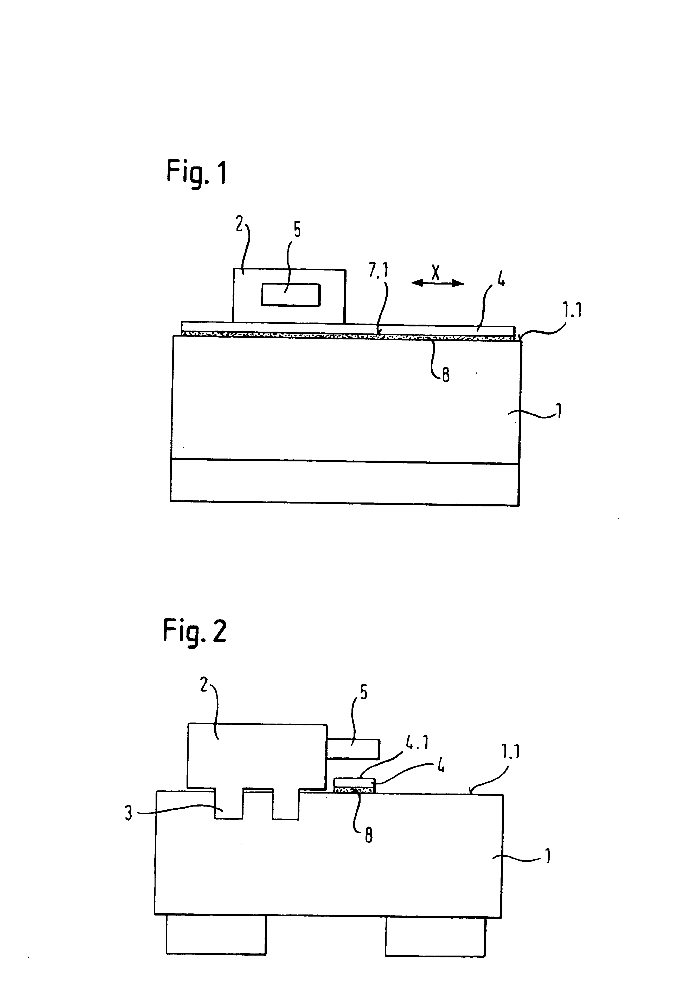
A coordinate-measuring machine, having a machine base 1 and a carriage 2, is represented in FIGS. 1 and 2. The carriage 2 can be displaced in a longitudinal direction X along a linear guide 3. A linear measuring system, including a scale 4 and a scanning head 5, is used for determining the position of the carriage 2 in relation to the base 1.

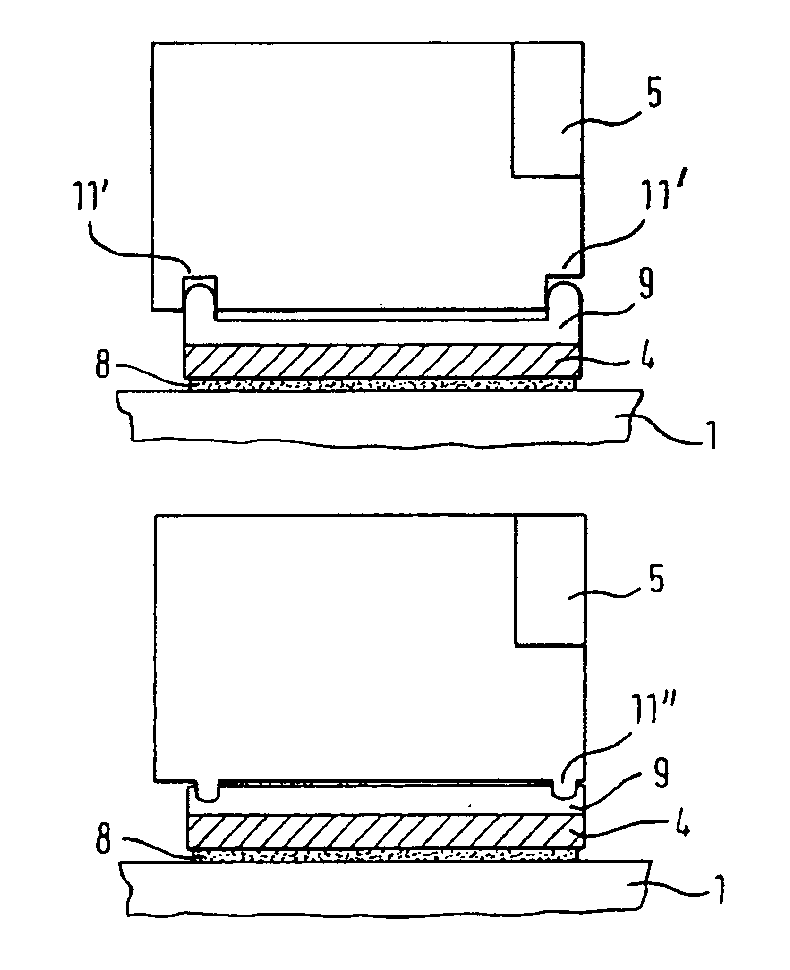
In the example represented in FIGS. 1 and 2, the scale 4 is a metal tape, which on its underside 7.1 is provided with a foil 8 with an adhesive on both sides.

So that in the course of the movement of the carriage 2 in relation to the bed 1 the scanning head 5 can continuously scan the graduation 4.1 of scale 4 in a contactless manner, the scale 4 must be fastened on the bed 1 parallel with the displacement direction X of the scanning head 5, and therefore of the carriage 2.

In accordance with the pres


PUM

PropertyMeasurementUnit
Adhesion strengthaaaaaaaaaa

Abstract

A device for the directional attachment of a scale element of a linear position measuring system to an installation face of a first body. The device includes a first body, a second body comprising a scanning head, which is movable in a measuring direction in relation to said first body, and a scale element is aligned parallel with respect to the measuring direction and a profiled alignment device is provided on the second body, which works together with a complementary tape profile on the scale element for aligning the scale element.

Description


Claims


Application Information

Patent Timeline
Owner DR JOHANNES HEIDENHAIN GMBH
Why Eureka
Try Eureka