Supplemental heat conduction path for card to chassis heat dissipation

a heat dissipation path and heat conduction path technology, applied in the direction of electrical apparatus construction details, mounting of support structures, lighting and heating apparatus, etc., can solve the problems of card and/or system failure, improper operation, card failure or system failure, etc., to increase the heat dissipation capacity of the frame 12. , the effect of increasing the conductive area or the path

Inactive Publication Date: 2005-03-29
DY 4 SYST
View PDF6 Cites 40 Cited by
  • Summary
  • Abstract
  • Description
  • Claims
  • Application Information

AI Technical Summary

Benefits of technology

This patented technology improves cooling efficiency by allowing more space within the case without adding extra parts like fans. It achieves this through two parallel channels that allow heat to be transferred across both sides of the case.

Problems solved by technology

This patent describes a technical problem related to cooling electronic equipment, particularly where there are multiple circuits installed together. To maintain the necessary performance levels, these circuits require efficient heat dissipation without overheating certain parts. Additionally, the current methods involve attaching separate heat sinks to the equipment, increasing its size and weight. There is a need for better ways to remove excess heat while minimizing any negative effects on the equipment.

Method used


Image

  • Supplemental heat conduction path for card to chassis heat dissipation
  • Supplemental heat conduction path for card to chassis heat dissipation
  • Supplemental heat conduction path for card to chassis heat dissipation

Examples


Embodiment Construction

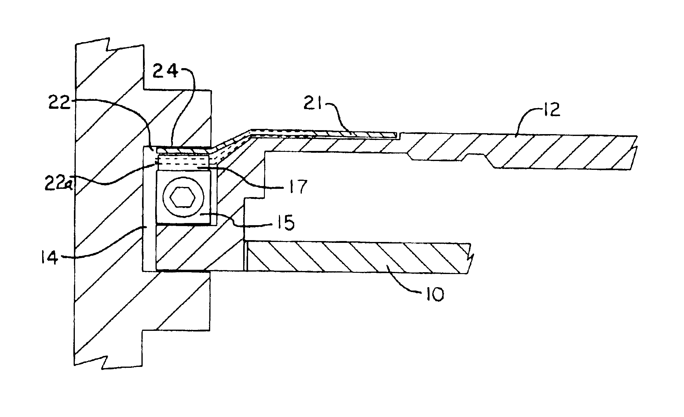
The heat plate 21 of the present invention, is made of rigid, semi-rigid or flexible, heat conductive material such as copper or an alloy commonly used in construction of heat dissipation frames. The plate is thin to allow for the flexibility necessary when the wedge lock 15 is moved into position. The flange 22 of the plate 21 can be a single continuous piece positioned between the wedge lock and the channel or it can have cut outs and notches to allow for greater flexibility. The upper segments 17 of the wedge lock 15 move laterally when the wedge lock is expanded and the heat plate must be constructed to accommodate the lateral movement of the wedge lock segments.

The heat plate 21, as illustrated in FIGS. 5, 6 and 7, extends between the wedge lock 15 and the wall of channel 14. As illustrated in FIG. 6B, flange 22 will flex slightly when the wedge lock is expanded to secure the card 10 into position. The plate 21 is constructed so that flange 22a, illustrated in broken line, is in c


PUM


Abstract

A heat dissipation element which can be shaped as a flat plate for transfer of heat to the opposite side of a mounting channel in a chassis for holding circuit cards. Circuit cards are typically held in place in channels in a chassis by an expansion type retention device. The circuit cards also include a heat frame for collecting the heat produced by the card components and channeling the heat from the card through the heat frame to the chassis. The retention device presses the heat frame in to thermal contact with one side of the channel. The heat dissipation plate is held in thermal contact with the other side of the channel, providing a second additional heat path to channel heat away from individual components, the circuit card and/or the heat frame.

Description


Claims


Application Information

Patent Timeline
Owner DY 4 SYST
Why Eureka
Try Eureka