Image processing apparatus, image processing method and storage medium
a technology of image processing and image processing method, which is applied in the direction of coding/ciphering apparatus, instruments, printing, etc., can solve the problems of deteriorating judgment precision, inability to check the output itself for presence/absence of watermarks, and often unstable gray lines
- Summary
- Abstract
- Description
- Claims
- Application Information
AI Technical Summary
Benefits of technology
Problems solved by technology
Method used
Image

Examples
first embodiment
(First Embodiment)
The first embodiment of the present invention will be described hereinafter with reference to the drawings.
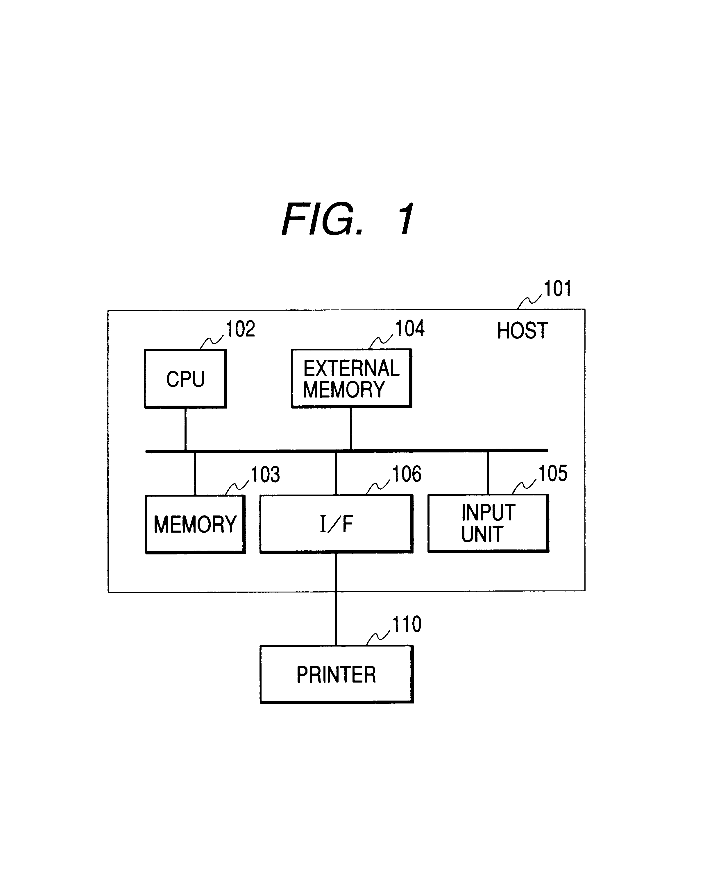
FIG. 1 is an explanatory view showing one example of an image processing system to which the present invention can be applied.
In FIG. 1, a host 101 is provided with a CPU 102, memory 103, external memory 104, input unit 105, and interface 106 with a printer 110. The CPU 102 executes a program stored in the memory 103 to realize detection, judgment, color processing, quantization processing, and the like of a digital watermark or another mark for specifying a printing inhibition image. This program is stored in the external memory 104, or supplied from an external apparatus. The external memory pre-stores a pattern to be detected. The pattern may be an invisible digital watermark for embedding information in a specific frequency of an image, a visible digital watermark for embedding the information by a color invisible to human eyes (e.g., yellow dot), or any othe
second embodiment
(Second Embodiment)
The second embodiment will be described hereinafter with reference to the drawings.
FIG. 3 is a block diagram showing the peripheral outline of the image processing by software executed by the program (printer driver) installed, for example, in the host computer.
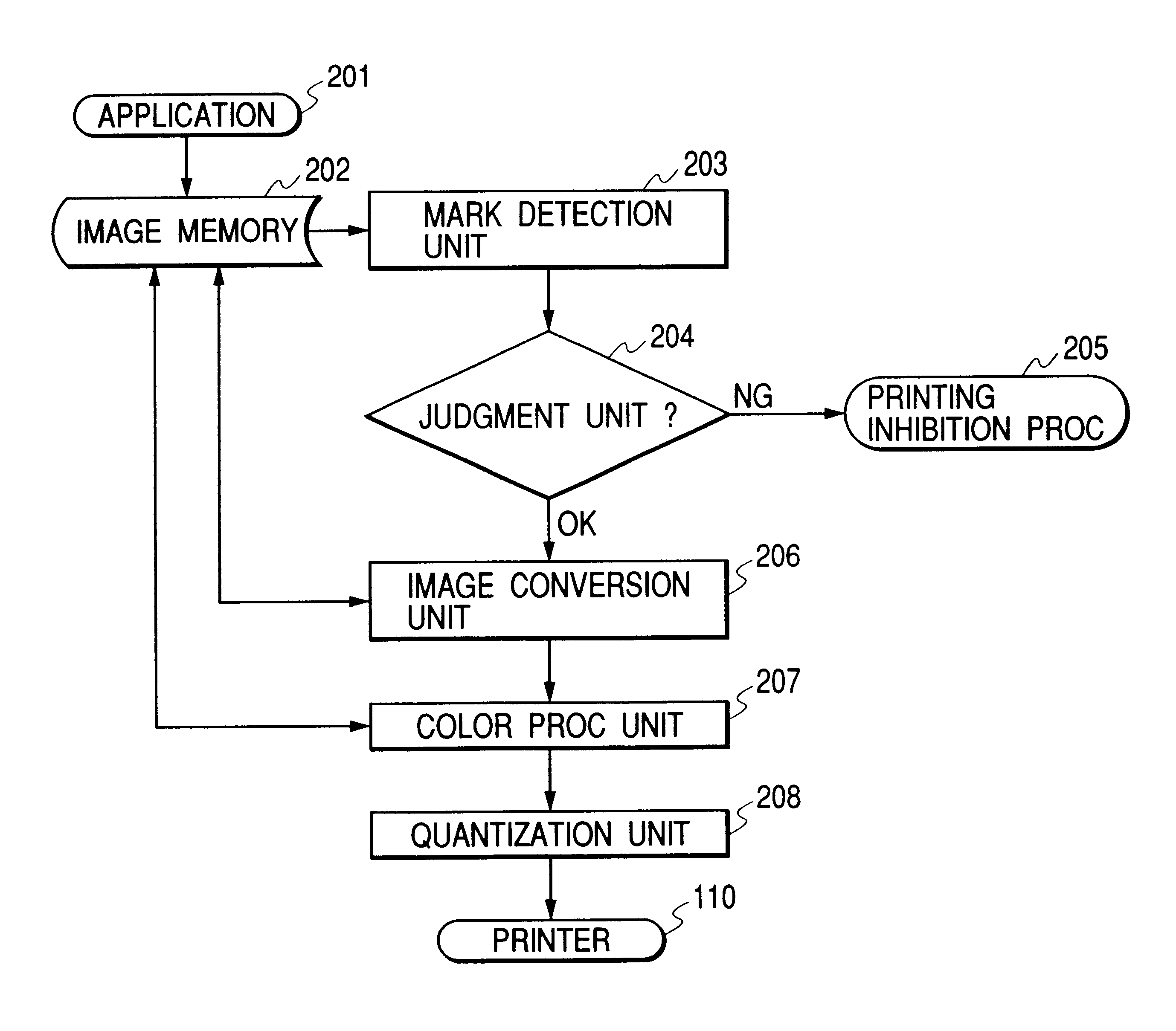
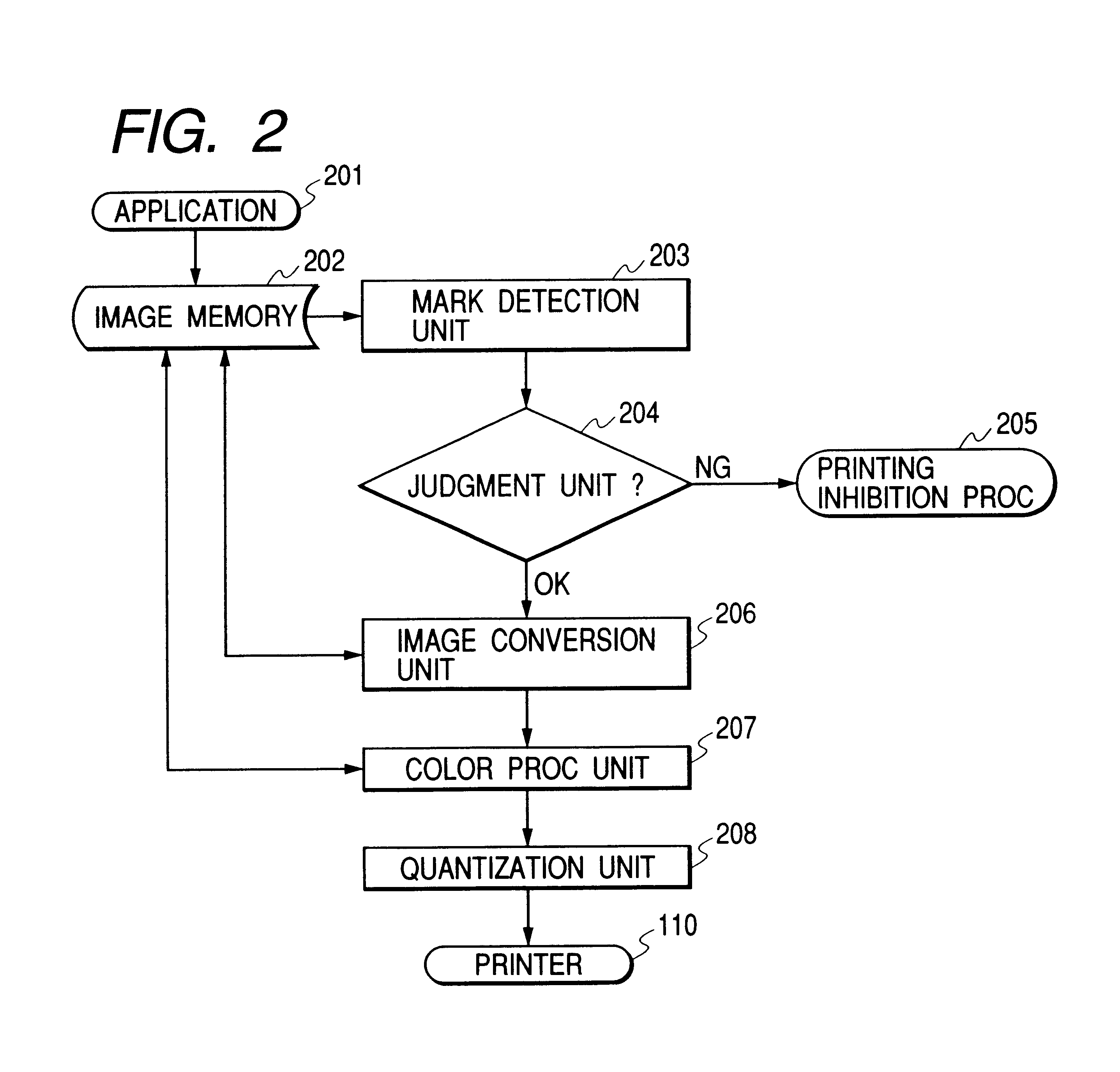
Based on the drawing command outputted from an application 301, the image information, for example, of respective 8 bits of RGB, that is, 24 bits rasterized in the image to be printed is stored in an image memory 302. The rasterizing may be performed in the application or the printer driver. For the RGB image stored in the image memory 302, a histogram creation unit 303 creates a histogram with respect to the respective channels of RGB as shown in FIG. 4. Here, as an element for creating the histogram, instead of RGB, the following calculation is performed, and the histogram may be created for the channel of YCC, or luminance Y out of the following.Y (luminance)=0.30R+0.59G+0.11BC1 (color difference)=R−YC2 (co
third embodiment
(Third Embodiment)
In the second embodiment, the histogram is created. However, for example, when the image data is particularly large, the creation of the histogram itself sometimes results in the increase of processing time. Therefore, the embodiment for judging that the data is not the paper money or the stamp with further simple means other than the histogram to further shorten the processing time will be described with reference to a block diagram of FIG. 5.
The image is rasterized to the image memory 302 from the application 301 in the same manner as described above, but an image data judgment unit 311 judges whether all the rasterized image data is only R=G=B=0 (black) or R=G=B=255 (white). If all the image data is R=G=B=0 or R=G=B=255, the data is only white and black, a document having the mark of the paper money, securities or the like cannot be considered, and the flow directly advances to the processing of a color processing unit 309. If one element of the image data is data
PUM
 Abstract
Description
Claims
Application Information
 - R&D Engineer
- R&D Manager
- IP Professional
- Industry Leading Data Capabilities
- Powerful AI technology
- Patent DNA Extraction
Browse by: Latest US Patents, China's latest patents, Technical Efficacy Thesaurus, Application Domain, Technology Topic.
© 2024 PatSnap. All rights reserved.Legal|Privacy policy|Modern Slavery Act Transparency Statement|Sitemap