Portable information input apparatus
a technology of information input and portable devices, which is applied in the field of information input apparatuses, can solve the problems of inconvenient data input, low data input process efficiency, and more complicated data entry of japanese letters with restricted number of keys on the keypad, and achieve the effect of improving the operability of data entry
- Summary
- Abstract
- Description
- Claims
- Application Information
AI Technical Summary
Benefits of technology
Problems solved by technology
Method used
Image

Examples
first embodiment
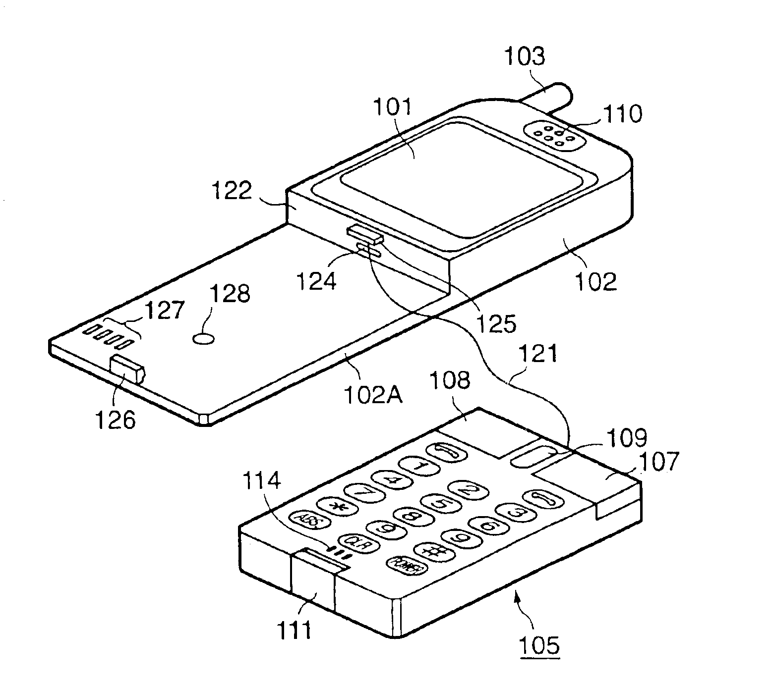
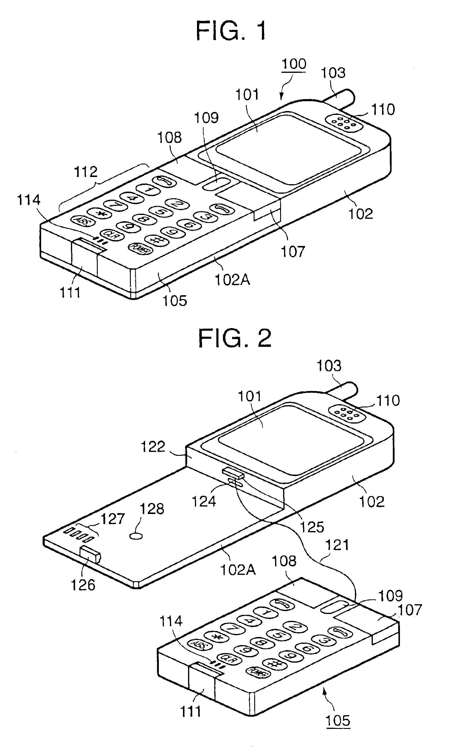
[0046]Referring to FIG. 1, a portable telephone set denoted by reference numeral 100 comprises a telephone set main body 102 having a display unit 101 disposed in its front face. The telephone set main body 102 includes an antenna 103 disposed in its upper end portion so as to be freely expanded / contracted.
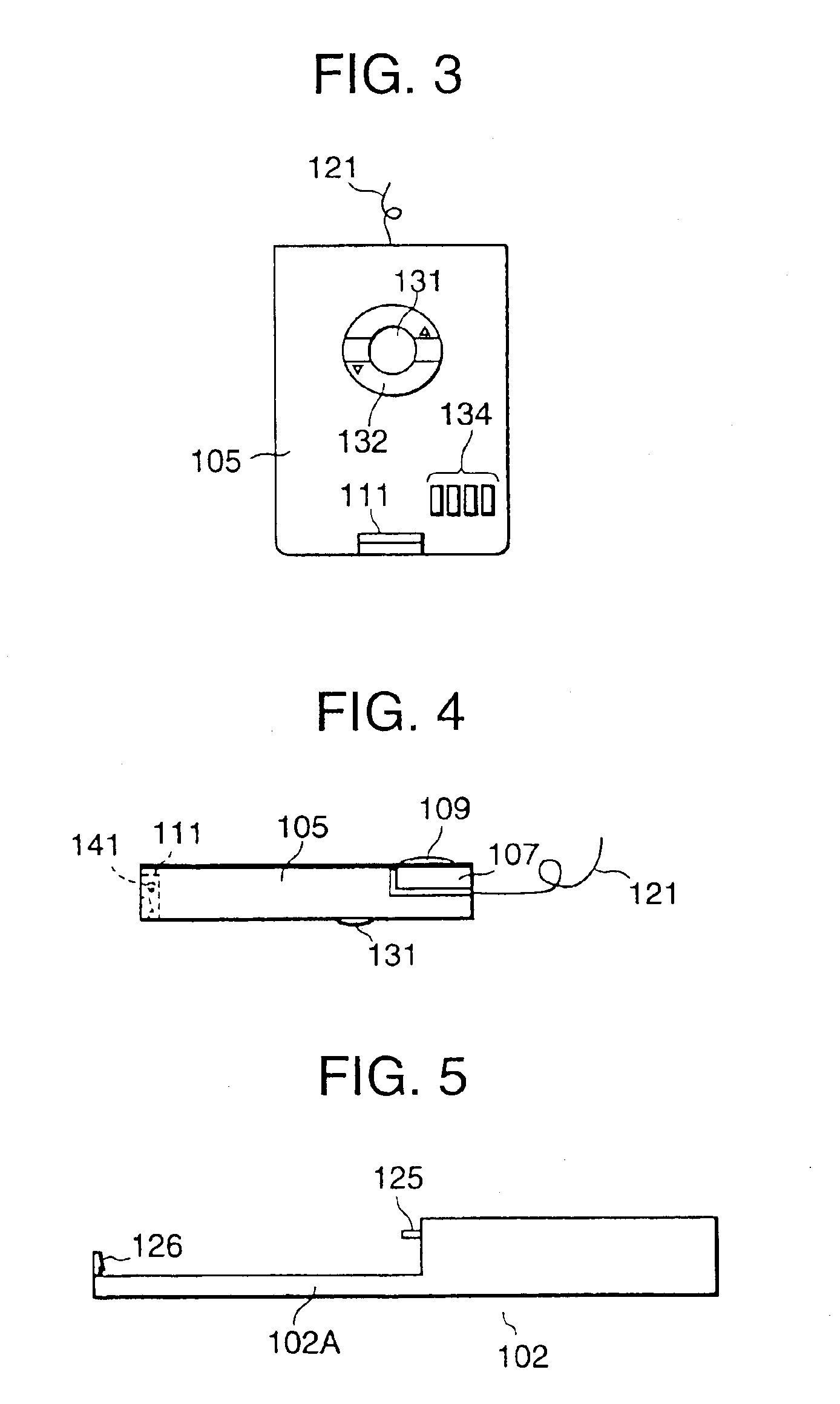
[0047]An operation unit 105 capable of functioning as a pointing device (here, a mouse) is detachably coupled to a level difference portion 102A located one-step lower in the telephone set main body 102. Right and left buttons 107 and 108 corresponding to right and left buttons of an ordinary mouse are disposed in the upper end portion of the front face of the operation unit 105. Further, the operation unit 105 is provided with a rotary wheel 109 located in the center portion thereof and a part of the rotary wheel 109 is protruded from the front face of the operation unit 105.
[0048]An operation unit locking mechanism 111 is attached near the lower end portion of the operation unit
first modified example
[0068]FIG. 7 shows a first modified example of the first embodiment of the invention. In FIG. 7, members similar to those described with reference to FIG. 1 are denoted by the same reference numerals, and the descriptions thereof will be omitted. In the first modified example, an upper-direction cursor key 161 is disposed immediately below the display unit 101 of the telephone set main body 102. A lower-direction cursor key 162 is also disposed adjacently to the rotary wheel 109 included in the keypad 112 of the operation unit 105. These upper-direction and lower-direction cursor keys 161 and 162 are not functioned in the mouse mode but in the normal mode. In this case, the right and left buttons 107 and 108 are used respectively as right-direction and left-direction cursor keys.
second modified example
[0069]FIG. 8 shows a second modified example of the first embodiment of the invention. In FIG. 8, members similar to those described with reference to FIG. 2 are denoted by the same reference numerals, and the descriptions thereof will be omitted. In the second modified example, an operation unit 105A has a cable 171 connected thereto and the cable 171 has a first connector 172 connectable to the telephone set main body 102. Therefore, the telephone set main body 102 and the operation unit 105A are connected to each other by the cable 171.
[0070]As shown in FIG. 9, in the second modified example, a second connector 174 is disposed in the partition wall 122. The connection of the first connector 172 to the second connector 174 allows not only a power-supply line connection but also a signal line connection between the telephone set main body 102 and the operation unit 105A.
[0071]FIG. 10 shows the backside of the operation unit in the second modified example. In FIG. 10, members similar t
PUM
 Abstract
Description
Claims
Application Information
 - R&D Engineer
- R&D Manager
- IP Professional
- Industry Leading Data Capabilities
- Powerful AI technology
- Patent DNA Extraction
Browse by: Latest US Patents, China's latest patents, Technical Efficacy Thesaurus, Application Domain, Technology Topic.
© 2024 PatSnap. All rights reserved.Legal|Privacy policy|Modern Slavery Act Transparency Statement|Sitemap