Method for dynamic allocation of wireless base station DSP resources

Inactive Publication Date: 2005-11-29
RATEZE REMOTE MGMT LLC
View PDF22 Cites 34 Cited by
  • Summary
  • Abstract
  • Description
  • Claims
  • Application Information

AI Technical Summary

Benefits of technology

[0019]The method also provides for handing over the call from a first cell of the BBS to a target cell of the same B

Problems solved by technology

When using a sectorized approach, the RF channels assigned to a particular BTS must be further allocated among each of the sectors, since interference can be caused if multiple sectors processed by the BTS are operated on the same frequency.
Thus, DSP units are not generally fungible as between sectors of a particular BTS, and therefore these DSP units cannot be allocated from one sector to another.
In cell sites that experience heavy traffic, this limitation can result in a poor allocation of system resources.
In particular, one of the problems with using sectorization in wireless base stations concerns trunking efficiency.
However, because the number of RF channels allocated to a sector is fixed in conventional BTS system, those resources are blocked and left unused, lowering the trunking efficiency of the base station.
How

Method used


Image

  • Method for dynamic allocation of wireless base station DSP resources
  • Method for dynamic allocation of wireless base station DSP resources
  • Method for dynamic allocation of wireless base station DSP resources

Examples


Embodiment Construction

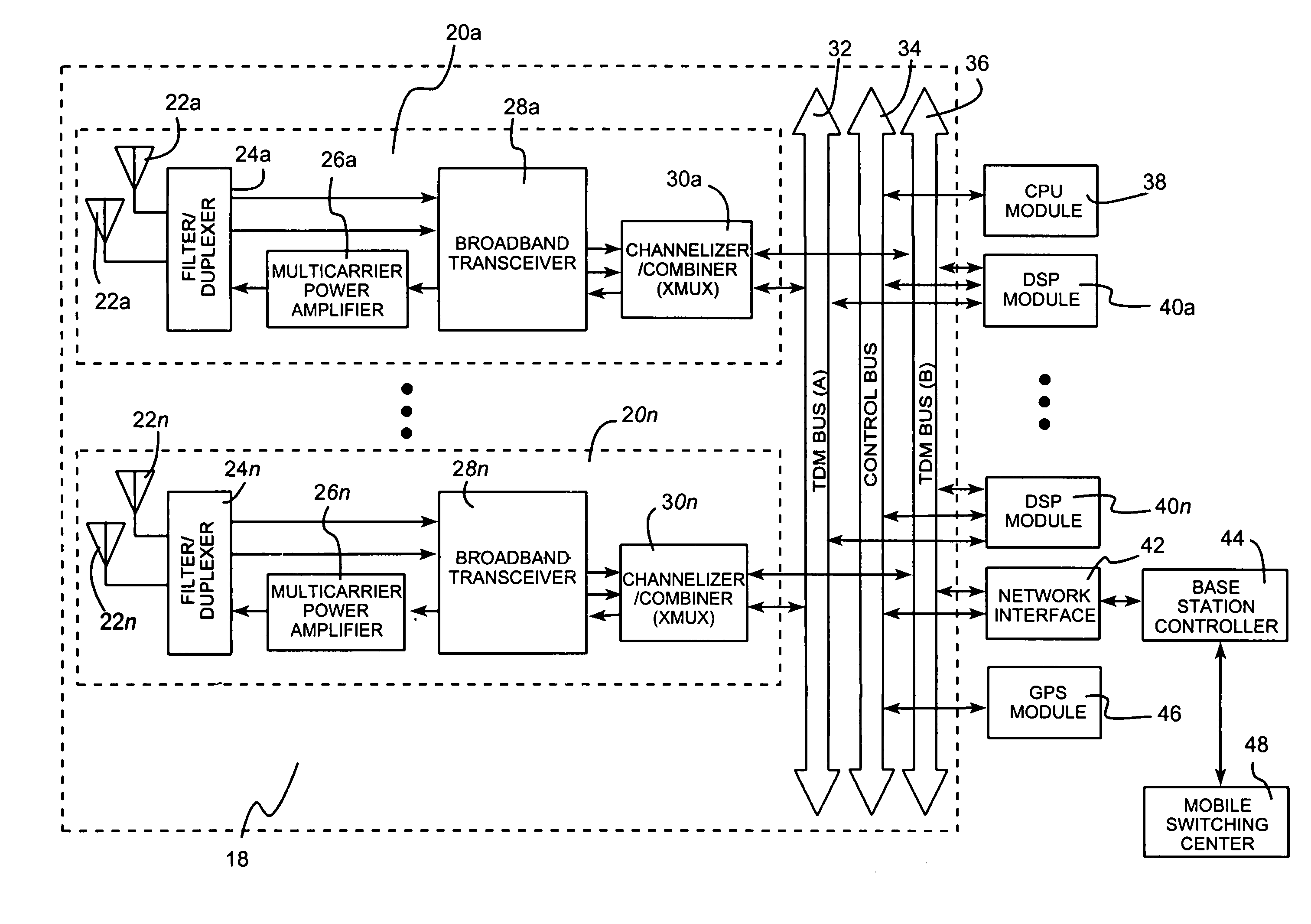
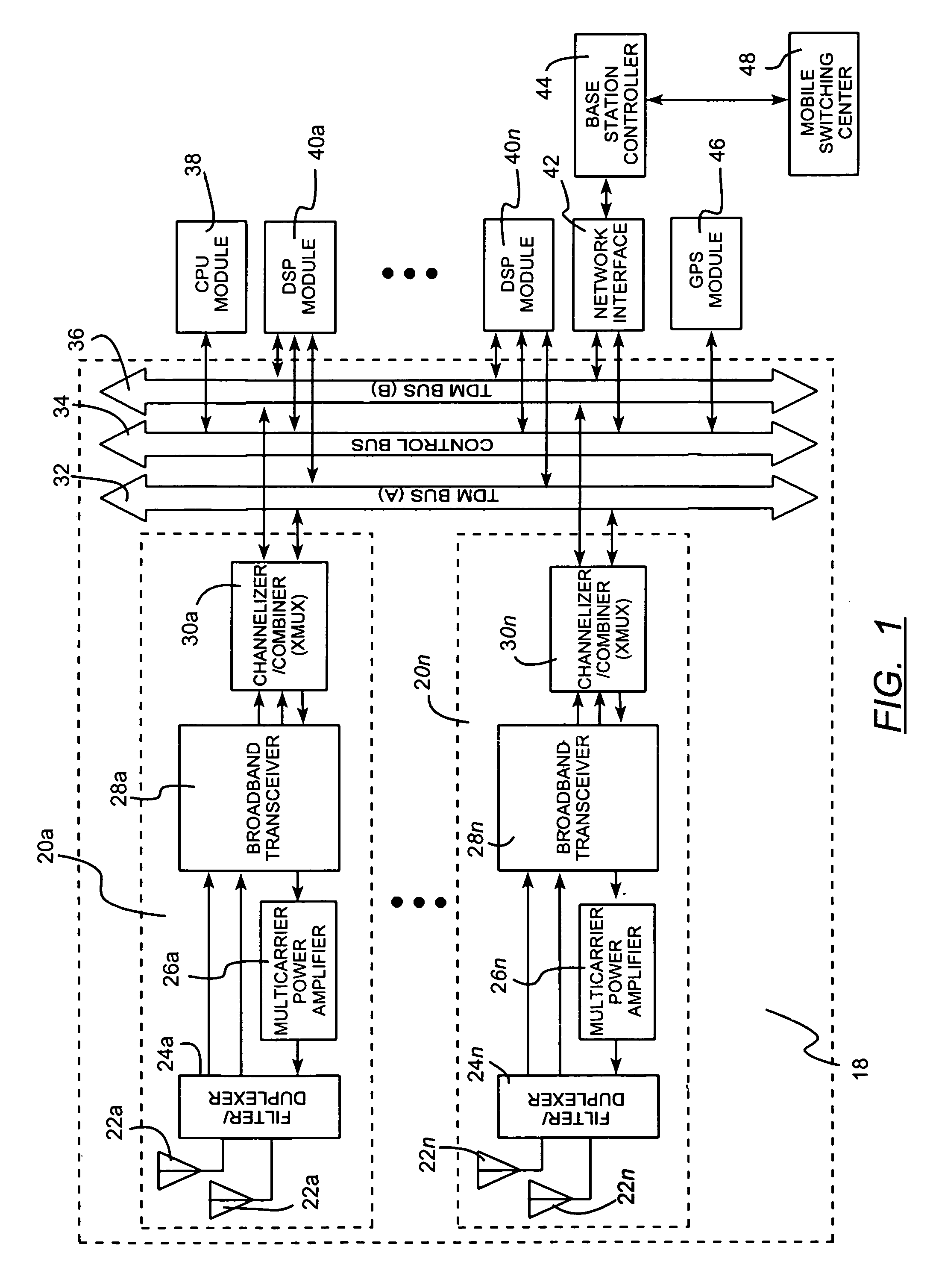
[0038]Referring to FIG. 1, a block diagram of an apparatus for increasing the number of calls processed by a base station, according to the present invention, is illustrated. A broadband base station (BBS) 18 communicates with a Base Station Controller (BSC) 44. The BSC 44 interfaces with multiple BBSs 18 for concentration of traffic to a Mobile Switching Center (MSC) 48. The BSC 44 performs mobility management and network interface management associated with mobile units as calls become active and terminate, as well as when mobile units move from the coverage area of one BBS 18 or cell to another.

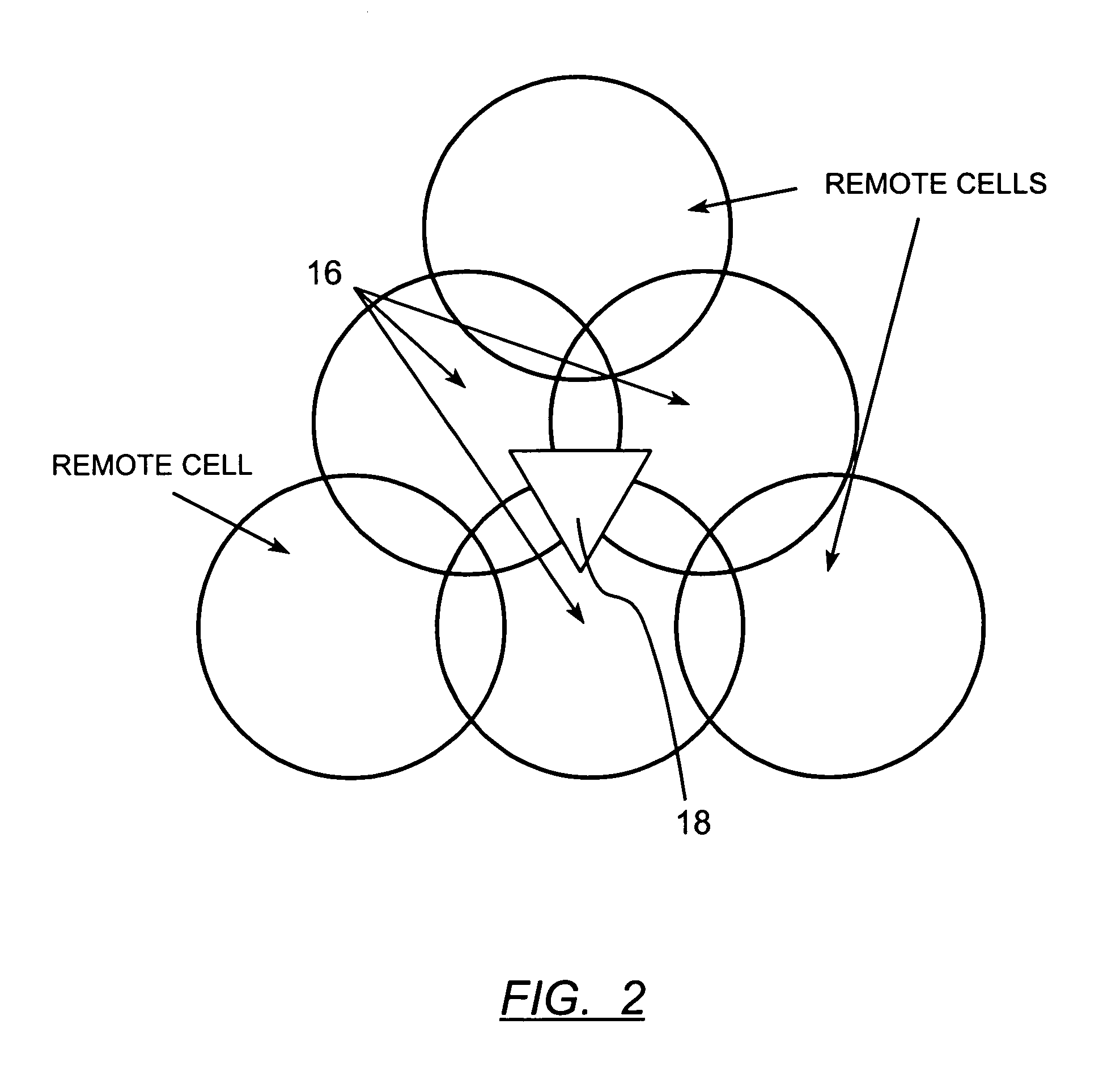
[0039]As shown in FIG. 2, the BBS 18 can support multiple sectors 14, each of which can support one or more cells 16. For each of the multiple sectors that the BBS 18 is separated into, the BBS 18 will contain a sector module 20a–20n. These sector modules 20a–20n will each have a set of two antennas 22a–22n, a filter / duplexer 24a–24n, a multicarrier power amplifier 26a–26n, a broadband tran


PUM


Abstract

A method for dynamically allocating signal processing resources in a wireless multichannel broadband base station (BBS) for a cellular communications network including determining a number of available channel processor (CP) resources which are unused in a BBS. In response to notification of a subscriber call to be processed by a cell of the BBS, a determination is made as to whether the number of available CP resources is at least one. If so, then the call is assigned to any available CP resource in the BBS. Each of the CPs in the BBS process any of a plurality of traffic channels contained on any frequency channel assigned to the BBS. In addition, an apparatus for practicing the method is disclosed.

Description


Claims


Application Information

Patent Timeline
Owner RATEZE REMOTE MGMT LLC
Why Eureka
Try Eureka