Wireless terminal device
- Summary
- Abstract
- Description
- Claims
- Application Information
AI Technical Summary
Benefits of technology
Problems solved by technology
Method used
Image

Examples
first embodiment
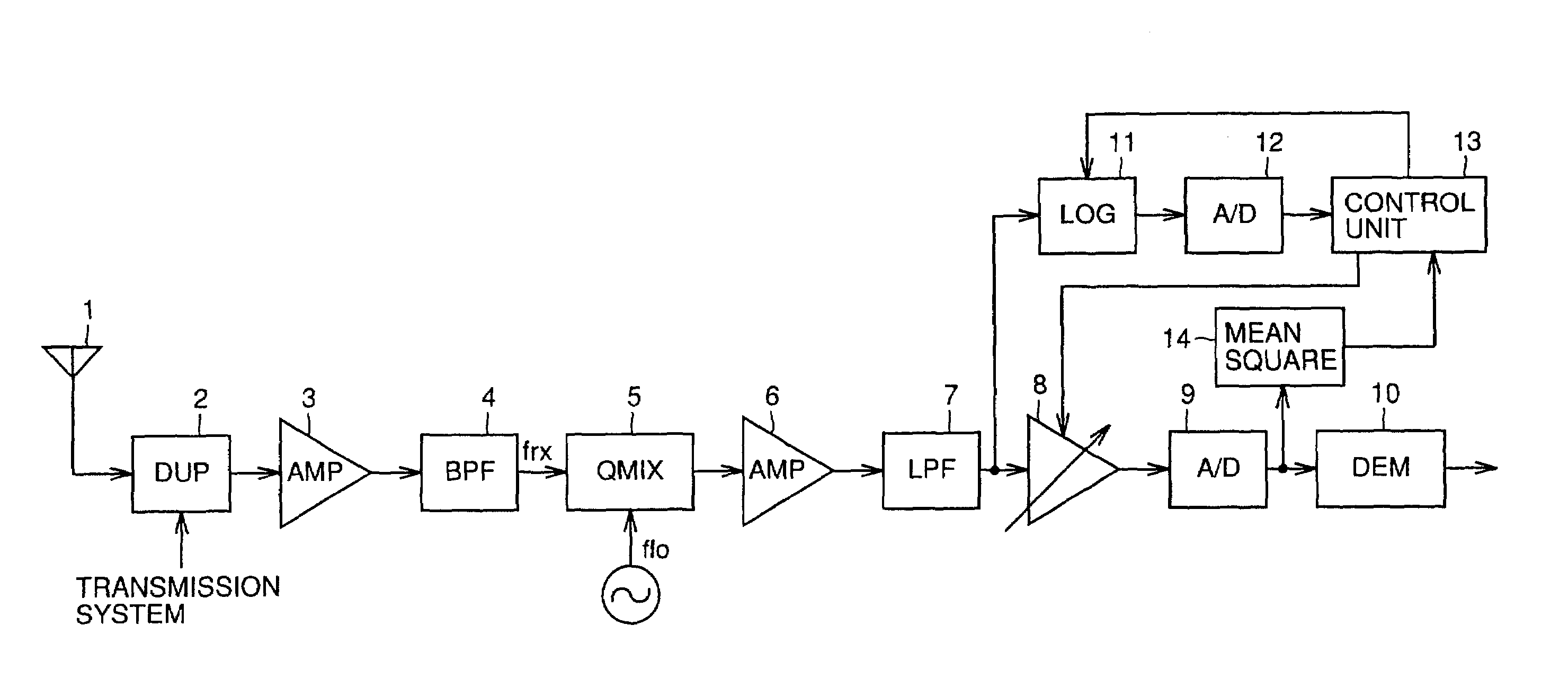
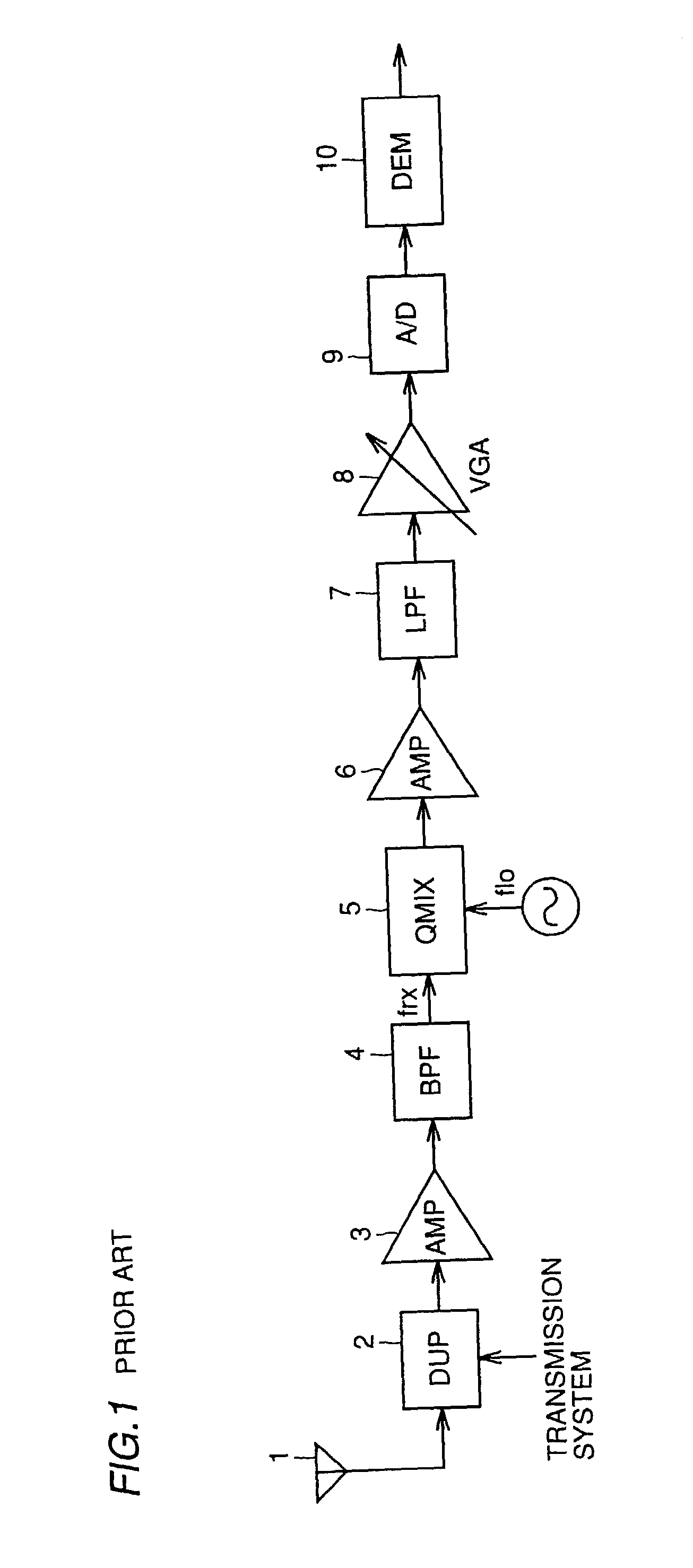
[0040]FIG. 3 is a block diagram of the present invention. In FIG. 3, the structure from an antenna 1 up to a demodulator 10 is same with that of FIG. 1. In this embodiment, a logarithmic amplifier 11, an A / D converter 12 and a control unit 13 are added. Logarithmic amplifier 11 detects a level of a base band signal supplied to variable gain amplifier 8. Here, logarithmic amplifier 11 does not detect the level of the input signal with a high accuracy but has a wide input voltage range even though with somewhat coarse accuracy. Here, the wide input voltage range is required to allow detection of input signals from a low level to a high level.
[0041]Here, the necessary detection range is a range in which a minimum bit number of A / D converter 9 required for the demodulation can be derived. (The required minimum bit number of A / D converter 9 is derived through test, simulation or the like and the kind of means utilized is not of importance here. The numerical value thereof is also diff
third embodiment
[0050]FIG. 7 is a block diagram of the present invention. In the embodiment shown in FIG. 7, the power is supplied to logarithmic amplifier 11 only at the start of the operation and when the feedforward control is finished the power supply to logarithmic amplifier 11 is cut off or reduced to decrease the current consumption. For this end, a control signal is supplied from control unit 13 to logarithmic amplifier 11.
[0051]FIG. 8 is a flow chart referenced for describing a specific operation of the embodiment shown in FIG. 7. Next, a specific operation of the embodiment shown in FIG. 7 will be described with reference to FIG. 8. When the operation starts, control unit 13 supplies power to logarithmic amplifier 11 at step S11 and then, the same operations as in steps S1 to S3 of FIG. 4 are performed in steps S12, S13 and S14 to control the gain of variable gain amplifier 9. Then at step S15, the power supply to logarithmic amplifier 11 is cut off or reduced.
[0052]Hence, in this embodiment
fourth embodiment
[0054]FIGS. 9A and 9B are diagrams referenced for describing the fourth embodiment which is a method for detecting, when a caller moves from one wireless area of one base station to a wireless area of an adjacent base station which movement is generally referred to as a hand-over, using a communication system such as CDMA, an electric wave for a securable line to the adjacent base station while securing a line to the base station and FIG. 10 is a flow chart referenced for describing the operation thereof.
[0055]When the portable telephone is used, the data amount transmitted between a base station and a caller is constant in a normal operation as shown in FIG. 9A. The caller, however,.sometimes moves from one wireless area of one base station to another wireless area of an adjacent base station. In this case, the level of the signal in the adjacent base station is not known. Hence, a level of a line is detected at certain intervals to allow securing of the adjacent base station other th
PUM
 Abstract
Description
Claims
Application Information
 - R&D Engineer
- R&D Manager
- IP Professional
- Industry Leading Data Capabilities
- Powerful AI technology
- Patent DNA Extraction
Browse by: Latest US Patents, China's latest patents, Technical Efficacy Thesaurus, Application Domain, Technology Topic.
© 2024 PatSnap. All rights reserved.Legal|Privacy policy|Modern Slavery Act Transparency Statement|Sitemap