Auto-compensation for control voltage range of vco at low power supply

Active Publication Date: 2019-12-19
LATTICE SEMICON CORP
View PDF0 Cites 0 Cited by
  • Summary
  • Abstract
  • Description
  • Claims
  • Application Information

AI Technical Summary

Benefits of technology

[0006]It is to be understood that the summary is not intended to identify key or essential features of implementations of the present disclosure, nor is it intende

Problems solved by technology

For VCOs in portable or wearable electronic devices, high frequency is less desired.
The VCOs

Method used


Image

  • Auto-compensation for control voltage range of vco at low power supply
  • Auto-compensation for control voltage range of vco at low power supply
  • Auto-compensation for control voltage range of vco at low power supply

Examples


Embodiment Construction

[0015]Hereinafter, the present disclosure will be discussed with reference to a plurality of embodiments. It should be understood that discussion of these embodiments is to enable a person of normal skill in the art to better understand and thereby implement the present disclosure, not implying any limitation to the scope of the present disclosure.

[0016]As used herein, the phrase “include(s)” and its variants shall be interpreted as an open term meaning “including but not limited to.” The phrase “based on” shall be interpreted as “at least partially based on.” The phrase “an embodiment” or “one embodiment” shall be interpreted as “at least one embodiment.” The phrase “another embodiment” shall be interpreted as “at least one other embodiment.” The phrases like “first” and “second” may refer to different or the same objects. The phrase “variation direction” shall be interpreted as direction of variation comprised of direction of increasing and direction of decreasing. Other definitions


PUM


Abstract

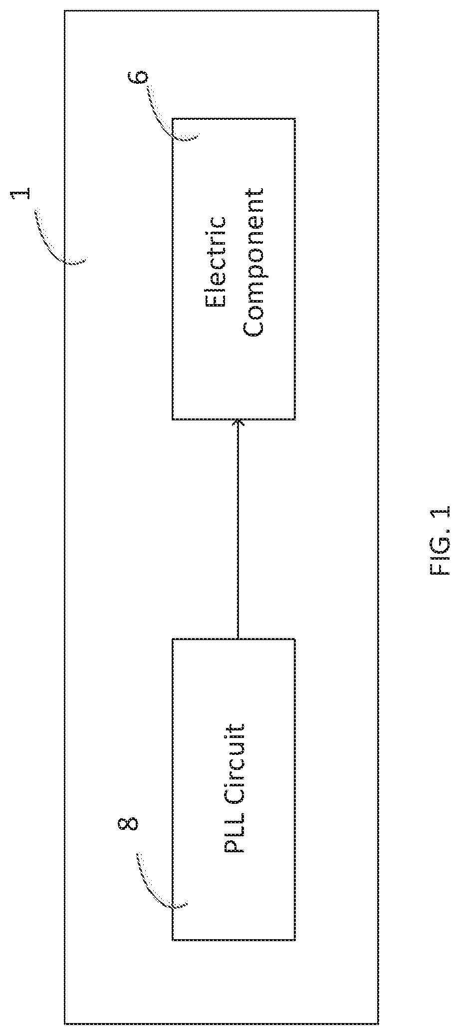
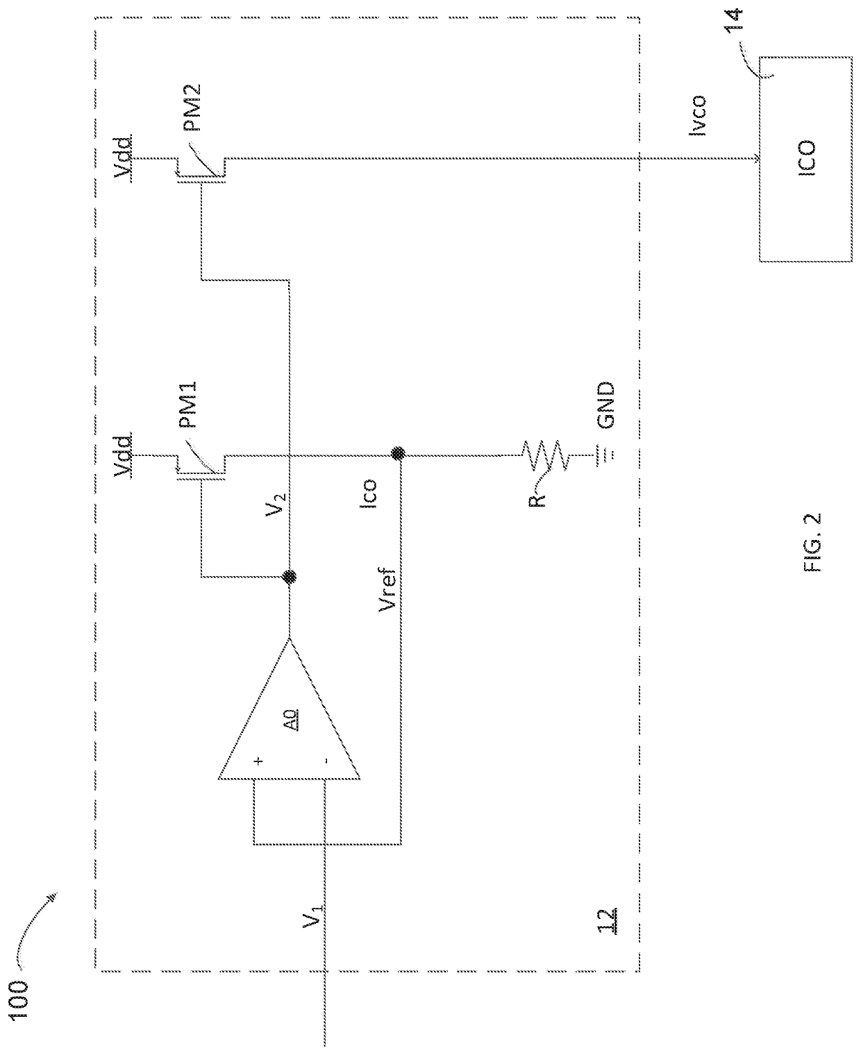
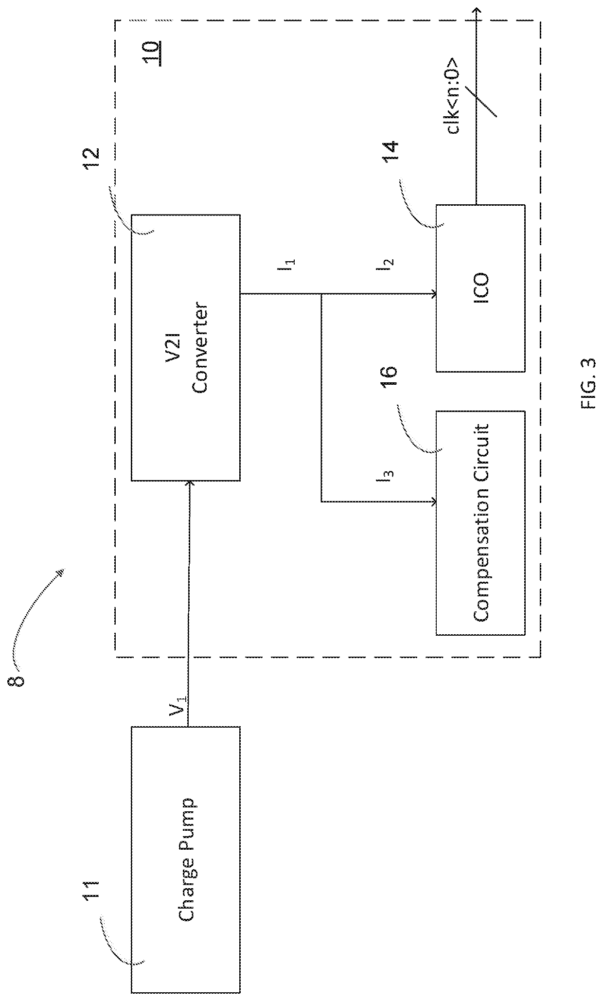
Some aspects of the present disclosure relate to an apparatus, a PLL and an electronic device. The apparatus comprises a voltage-to-current (V2I) converter, a current controlled oscillator and a compensation current. The V2I converter is operable to receive a first voltage and generate a first current based on the first voltage. The current controlled oscillator is coupled to the V2I converter and operable to generate an oscillation signal based on a second current from or to the V2I converter. The compensation circuit is coupled to the V2I converter and operable to receive a third current from or to the V2I converter. The second and third currents vary in response to at least one of temperature variation and supply voltage variation of the apparatus. Variation direction of the third current is opposite to variation direction of the second current and different frequencies may be provided for a low supply voltage domain.

Description


Claims


Application Information

Patent Timeline
Owner LATTICE SEMICON CORP
Why Eureka
Try Eureka