Charger and charging method thereof

A charger and charging current technology, applied in current collectors, electrochemical generators, battery circuit devices, etc., can solve problems such as self-protection status not working, adapter damage, etc.

Active Publication Date: 2018-12-21
SHENZHEN LANHE TECH CO LTD
View PDF6 Cites 2 Cited by
  • Summary
  • Abstract
  • Description
  • Claims
  • Application Information

AI Technical Summary

Problems solved by technology

However, when the power required by the mobile phone itself is large, the wireless charger will work according to the high power required. Correspondingly, the wireless charger will req

Method used


Image

  • Charger and charging method thereof
  • Charger and charging method thereof
  • Charger and charging method thereof

Examples


Embodiment Construction

[0025] In order to facilitate a better understanding of the purpose, structure, features, and effects of the present invention, the present invention will now be further described in conjunction with the accompanying drawings and specific embodiments.

[0026] Embodiments of the present invention are described in detail below, examples of which are shown in the drawings, wherein the same or similar reference numerals denote the same or similar components or components having the same or similar functions throughout. The embodiments described below by referring to the figures are exemplary and are intended to explain the present invention and should not be construed as limiting the present invention.

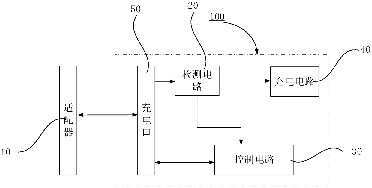
[0027] figure 1 It is a structural block diagram of the charger 100 according to an embodiment of the present invention. The charger 100 includes at least one charging port 50 , through which the charger 100 can be connected to the output terminal of the adapter 10 , so that the ad


PUM


Abstract

A charger includes a charging port for receiving an electrical signal input from an adapter. The charger further includes a detection unit electrically connected to the charging port and a control unit electrically connected to the detection unit. The detection unit detects an input voltage and an input current of the charger. The control unit judges whether the input voltage of the charger is within a preset voltage range, and when the input voltage of the charger is judged to be within the preset voltage range, the control unit controls the input current of the charger to gradually increasein a preset manner until the charger inputs maximum power so as to charge the charger. The invention also provides a charging method of a charger. By utilizing the invention, the input current level of the charger can be gradually increased until the charger inputs the maximum power, and the maximum power output of the adapter can be realized on the premise of guaranteeing the safety of the adapter.

Description


Claims


Application Information

Patent Timeline
Owner SHENZHEN LANHE TECH CO LTD
Why Eureka
Try Eureka