Display device having a plurality of pixels having different luminosity characteristics

a technology of luminosity characteristics and display devices, applied in the field of display devices, can solve the problems of increasing the size of the display device circuit, difficult to achieve coincidence between these characteristics of luminous elements, and inability to achieve low power consumption, so as to achieve uniform display without increasing the number of circuit components

Inactive Publication Date: 2006-04-18
KK TOSHIBA
View PDF7 Cites 16 Cited by
  • Summary
  • Abstract
  • Description
  • Claims
  • Application Information

AI Technical Summary

Benefits of technology

The technical effect of this patented technology relates to providing an improved way to make displays with uniform colors by elimining complex circuits needed due to variations between different types or sizes of light-emitting diodes (LEDs). This results in more efficient use of space on electronic devices while still maintaining consistently high quality images.

Problems solved by technology

The technical problem addressed in this patents relates to improving the performance and cost efficiency of flat panel display systems while maintaining consistent grayscale levels across multiple colored lights. Current methods involve adjustment of brightness based on factors like ambient temperature and humidity, but they cannot achieve complete agreement among all possible combinations of LEDs forming specific patterns. Therefore there needs an improved method called threshold voltage correction circuitry to improve the accuracy and reduce variations caused by environmental conditions during manufacturing processes.

Method used


Image

  • Display device having a plurality of pixels having different luminosity characteristics
  • Display device having a plurality of pixels having different luminosity characteristics
  • Display device having a plurality of pixels having different luminosity characteristics

Examples


Embodiment Construction

[0023]An organic EL display device according to one embodiment of the present invention will be described with reference to the accompanying drawings.

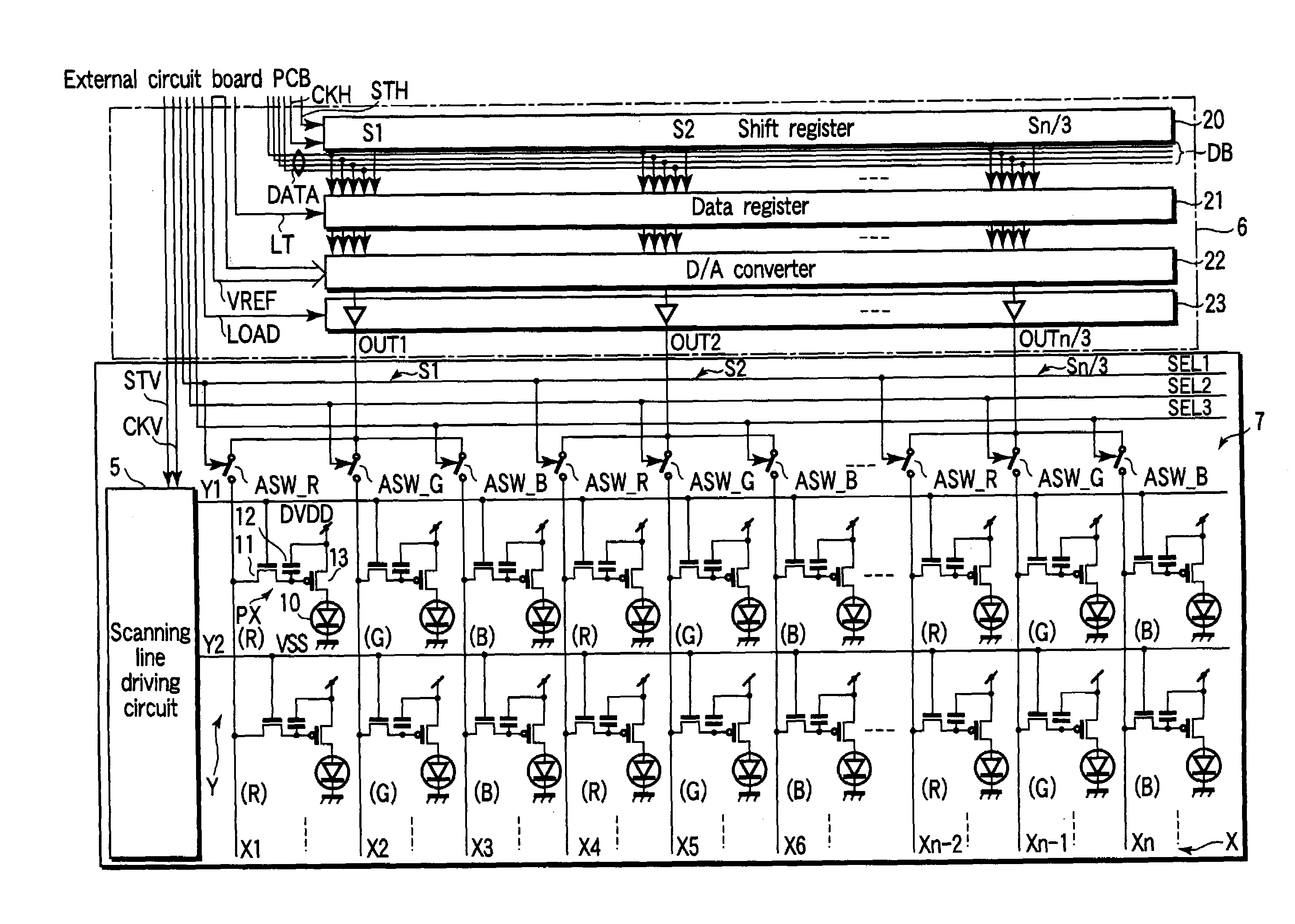
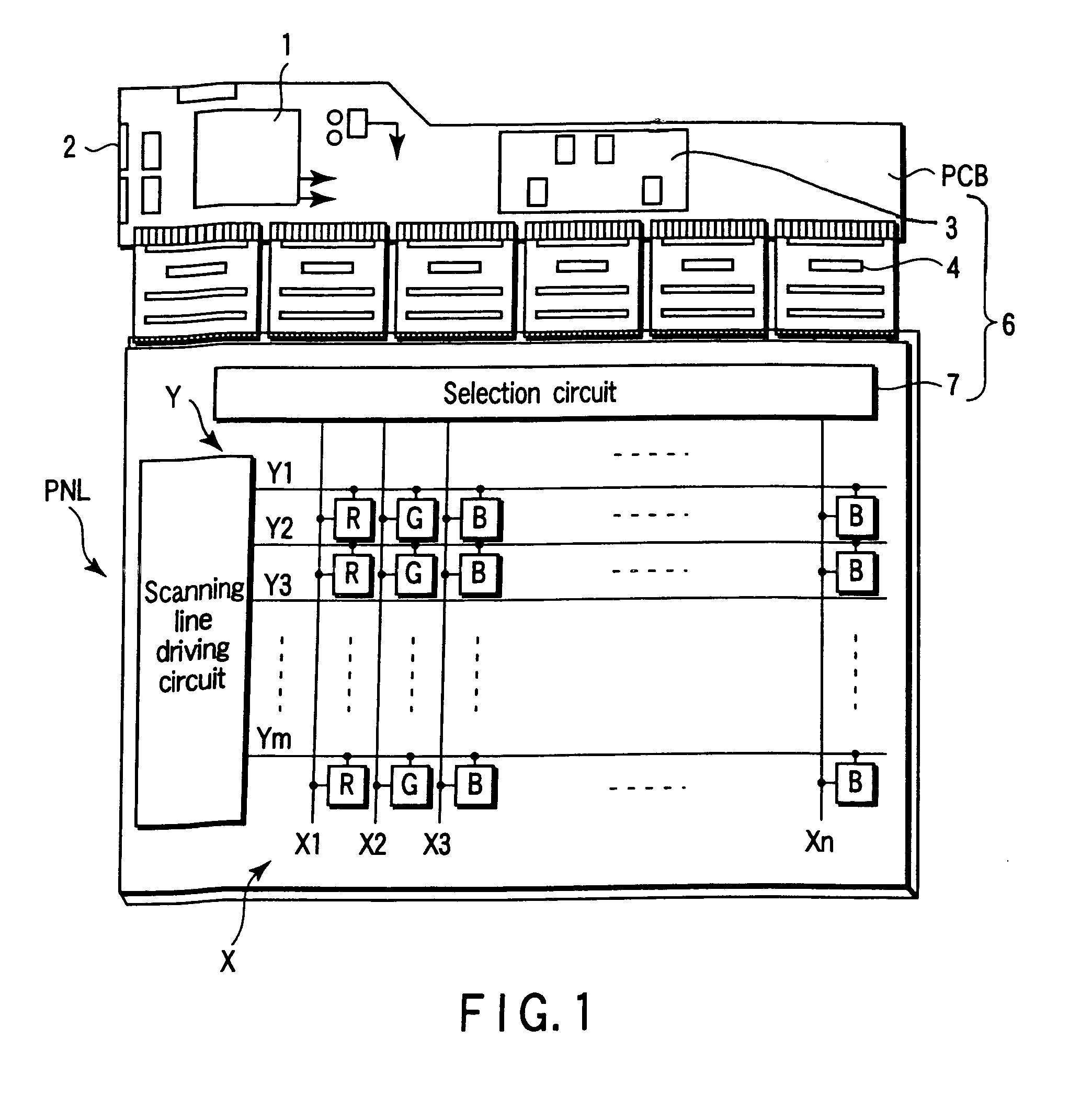
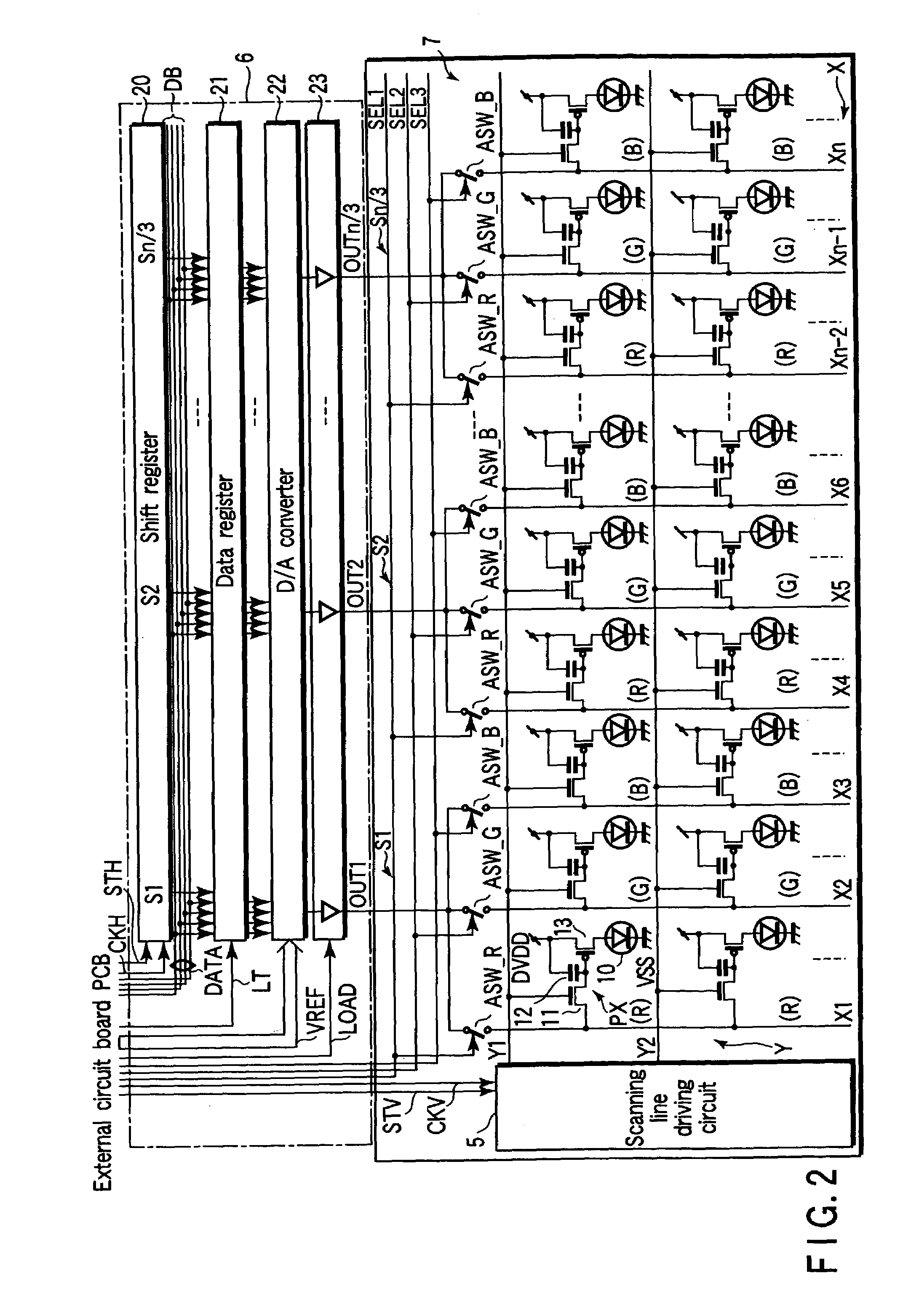
[0024]FIG. 1 schematically shows the planer structure of the active matrix organic EL display device, and FIG. 2 shows the circuit configuration of one part of the organic EL display device in detail.

[0025]This organic EL display device comprises an organic EL display panel PNL and an external circuit board PCB.

[0026]The external circuit board PCB includes a control section 1, a DC / DC converter 2, and a reference gradation voltage generating circuit 3. The control section 1 is formed of an IC chip which receives a digital video signal output from a signal source such as a personal computer, generates various control signals to drive the organic EL display panel PNL, and performs a digital process of changing the order of the digital video signal, for example. The DC / DC converter 2 generates different kinds of power supply voltages. Th


PUM


Abstract

A display device comprises pixels PX each of which has one of different luminosity characteristics, signal line blocks each including a preset number of signal lines X connected to the pixels PX having a common one of the luminosity characteristics, and a signal line driving circuit which drives the signal lines X according to a video signal. Particularly, the signal line driving circuit includes a selection circuit which sequentially selects the signal line blocks in an effective picture period of the video signal and an external driving unit which drives the preset number of signal lines included in the signal line block selected by the selection circuit.

Description


Claims


Application Information

Patent Timeline
Owner KK TOSHIBA
Why Eureka
Try Eureka