Electropneumatic control valve comprising a guide arrangement for a control piston

Inactive Publication Date: 2006-06-13
KNORR-BREMSE SYST FUER NUTZFAHRZEUGE GMBH
View PDF14 Cites 2 Cited by
  • Summary
  • Abstract
  • Description
  • Claims
  • Application Information

AI Technical Summary

Benefits of technology

[0015]The advantage of the invention is particularly the special further development of the guiding sleeve to be used, which provides a precise guiding function for the control piston as well as an effective outgoing-air guidance. Because of the particularly long bleeder duct which extends directly to the bleeder connection over the area of the valve seat arrangement, the opening of the bleeder duct arrives in an area of a lower ram pressure, whereby, because of the low existing counterpressure in the proximity of the bleeder connection, a bleeding of the control chamber is achieved which is faster despite the relative small diameter of the bleeder duct. Surprisingly, the tube section situated in the outgoing-air flow of the working chamber results in an extreme noise reduction during the bleeding of the brake line.
[0016]In order to further minimize the noise caused by the outflowing air at the electropneumatic control valve, a sound absorber can, in addition, be mounted on the bleeder connection. In cooperation with the sound absorber, the distal end of the tube section of the guiding sleeve has a fissured construction in order to ensure a free flowing-out of the outgoing air from the bleeder duct. As a result of this arrangement, a very low noise level is achieved on the whole which meets even strict requirements with respect to a control valve of the above-mentioned type.
[0017]Preferably, the guiding sleeve according to the invention, at least in the area of the guiding section, consists of a plastic material with a low sliding friction coefficient. As a result, a low sliding friction is achieved which is favorable for the axial guidance because the control piston, as a friction partner, preferably is also produced of a plastic material. It is also conceivable to use different pairings of material. The corresponding passage bore in the control piston, to this extent, can also be equipped with a Teflon bush or the like.
[0018]According to another embodiment of the invention, a guide pin formed in the pilot valve housing is provided for fastening the guiding sleeve, in which case, by way of a force-locking press fit, a connection with the guiding sleeve is established. Corresponding with the guide pin, in the area of the guiding section, the guiding

Problems solved by technology

However, the pneumatic control is mostly utilized only for safety purposes in the event of a failure of the electric control.
However, this type of guidance has the disadvantage that the guide bore in the pilot valve housing must be produced in a highly precise manner and with a high surface quality in order to avoid a jamming or tilting of the control piston within the cylindrical hollow space during the operation.
Furthermore, this known guiding arrangement causes a relativel

Method used


Image

  • Electropneumatic control valve comprising a guide arrangement for a control piston
  • Electropneumatic control valve comprising a guide arrangement for a control piston
  • Electropneumatic control valve comprising a guide arrangement for a control piston

Examples


Example

DETAILED DESCRIPTION OF THE DRAWINGS

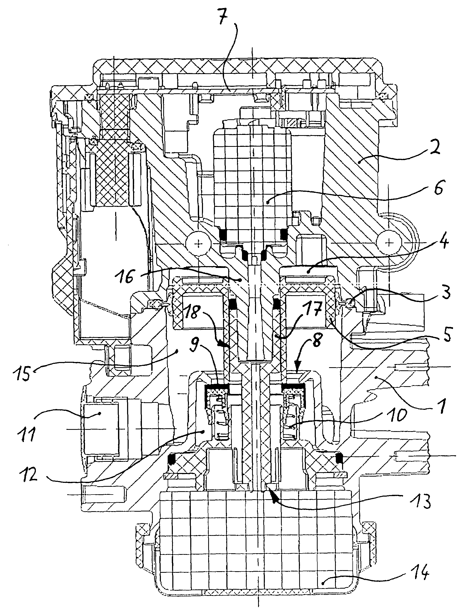
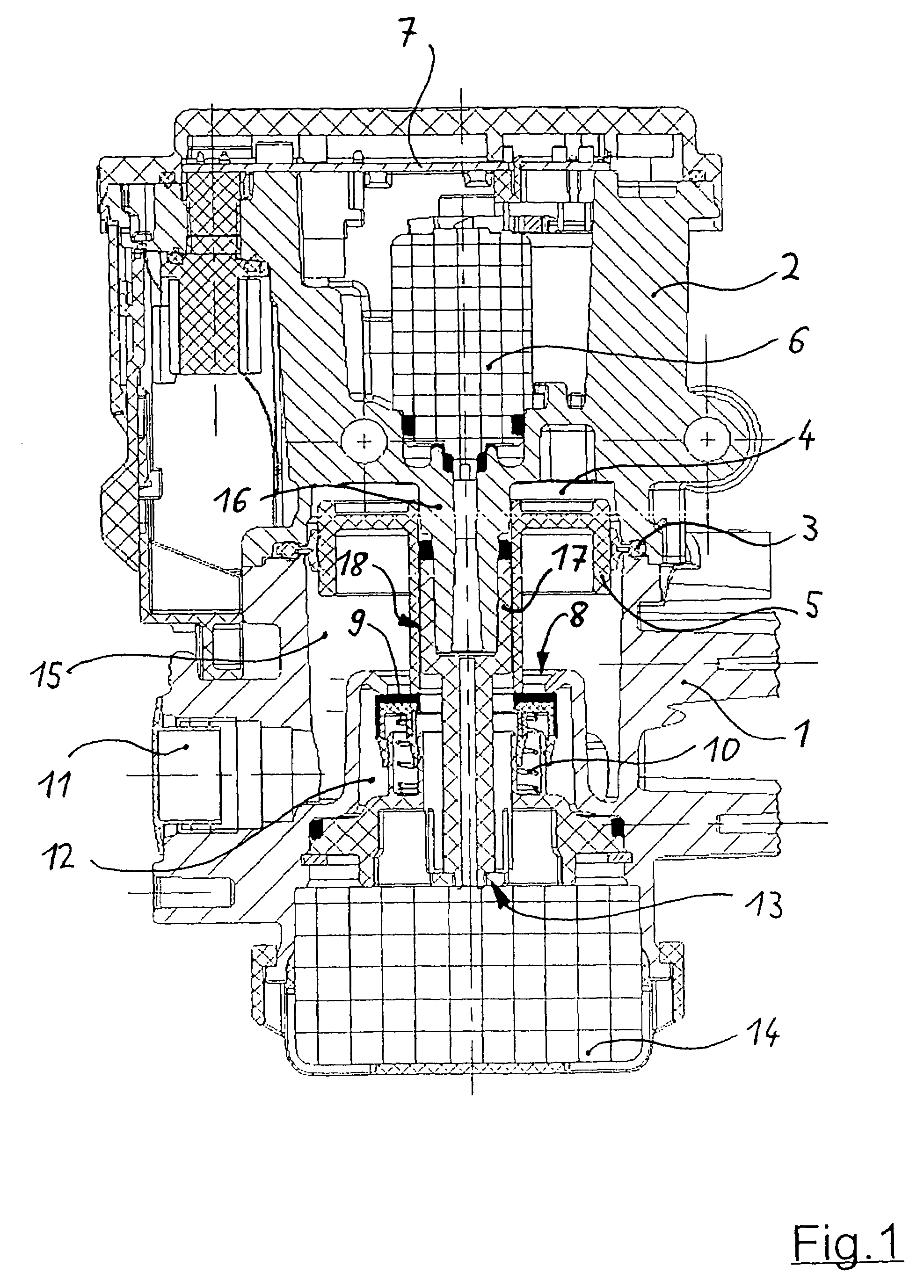
[0025]The electropneumatic control valve according to FIG. 1 has a housing arrangement which is essentially constructed in two parts and which consists of a lower relay valve housing 1 which is connected with an upper pilot valve housing 2, with sealing element 3 situated in-between. The connection takes place by means of a (not shown) screwed connection. The relay valve housing 1 and the pilot valve housing 2 enclose an interior control chamber 4 in which a control piston 5 is axially movably arranged. For the axial adjustment of the control piston 5, a pilot valve arrangement is used which is accommodated in the pilot valve housing 2 and of which only a pilot valve 6 is illustrated here. The pilot valve arrangement is electrically controlled here by means of an electronic unit. The illustrated pilot valve 6 is used as an outlet valve and, when operated, bleeds the control chamber 4, in which case the outgoing air is discharged to the atmosphere. In


PUM


Abstract

Electropneumatic control valve for a pneumatic brake system of a vehicle having a relay valve housing in which an axially adjustable control piston is arranged for actuating a valve seat arrangement which switches the compressed-air flow between at least one exterior brake line connection, a supply pressure connection and a bleeder connection. The control piston is axially guided by means of a coaxial guiding arrangement. The guiding arrangement comprises a separate guiding sleeve which is stationarily fastened to the pilot valve housing and which is provided with an upper guiding section which, for the axial guidance, corresponds with a passage bore in the control piston, and which, in addition, has a lower tube section of a smaller outside diameter adjoining the upper guiding section in order to guide the outgoing air flowing through an integrated axial bleeder duct directly to the bleeder connection.

Description


Claims


Application Information

Patent Timeline
Owner KNORR-BREMSE SYST FUER NUTZFAHRZEUGE GMBH
Why Eureka
Try Eureka