Waste treatment apparatus with integral membrane apparatus

a technology of wastewater treatment and membrane, applied in the direction of multi-stage water/sewage treatment, liquid displacement, separation process, etc., can solve the problems no aeration or biological treatment of membranes, and a large amount of bacteria, so as to achieve the effect of low electrical power consumption, minimal control, and easy operation

Active Publication Date: 2007-10-02
H2O INNOVATION USA INC
View PDF31 Cites 20 Cited by
  • Summary
  • Abstract
  • Description
  • Claims
  • Application Information

AI Technical Summary

Benefits of technology

This technology uses an Activated Sludge / Fixed Film method combined with biotic filters that can help clean water from harmful substances like plankton or other organic matter found on our streets during construction work hours. These methods have proven effective at removing these pollutants without requiring much energy input compared to traditional biological processes such as sedimentation basins.

Problems solved by technology

This patented technical problem addressed in this patents relates to improving the efficiency at treating sewage with active slurry processors such as activating sludges or immobilization membranes. Specifically, current methods involve adding different components separately during operation, leading to increased particulate levels due to incomplete breakdowns caused by poor mixing between these two phases.

Method used


Image

  • Waste treatment apparatus with integral membrane apparatus
  • Waste treatment apparatus with integral membrane apparatus
  • Waste treatment apparatus with integral membrane apparatus

Examples


Embodiment Construction

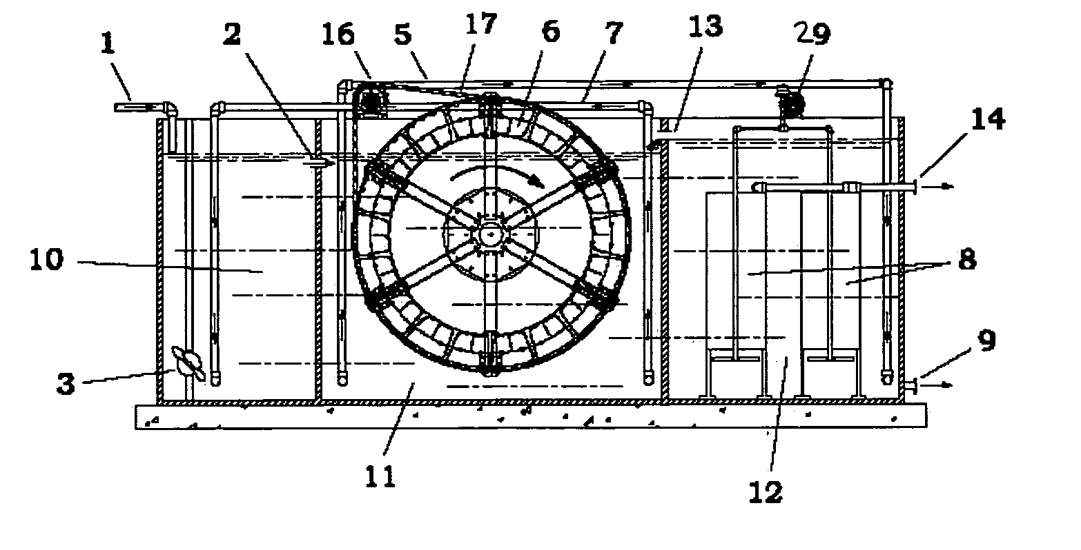
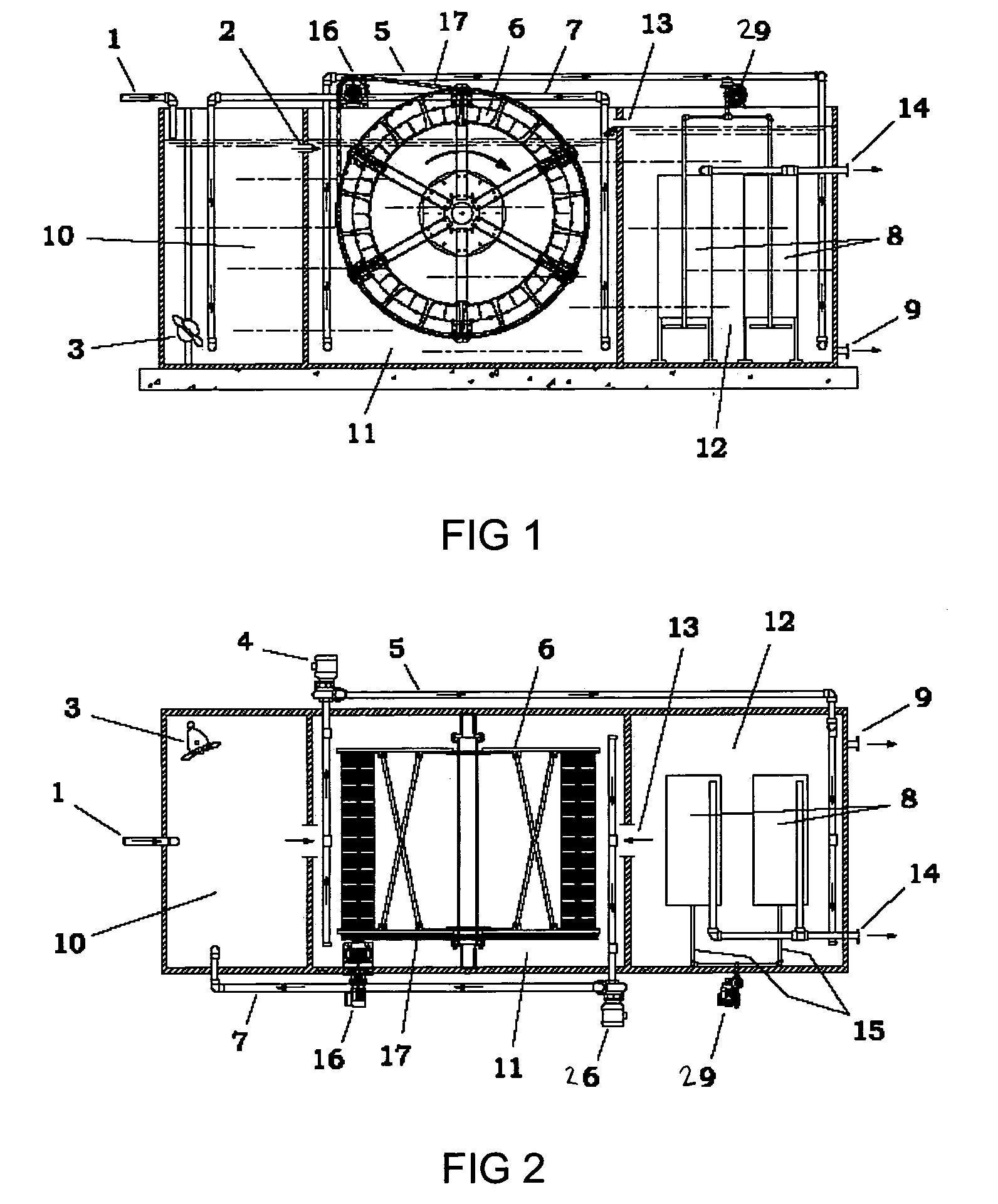
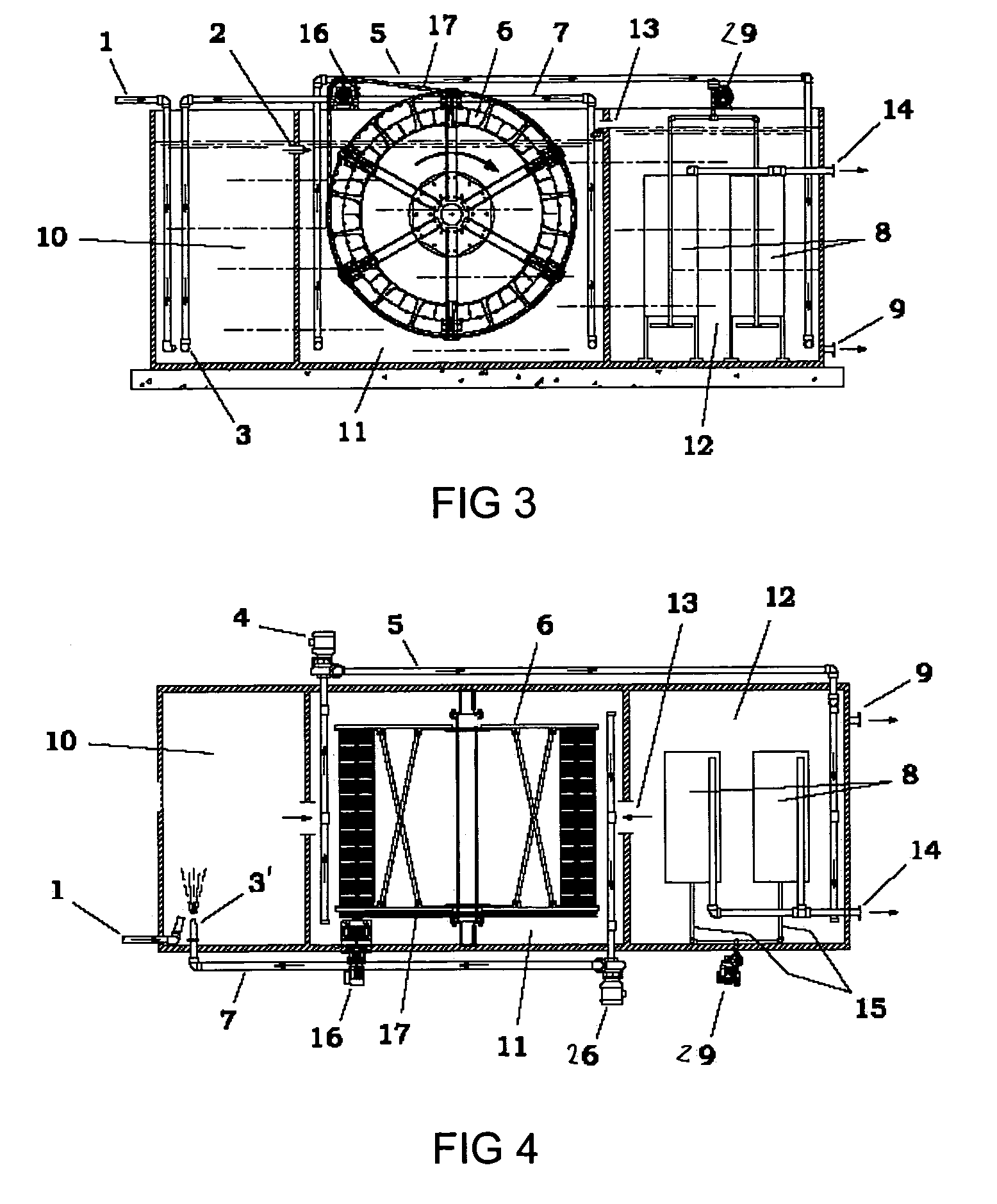
[0021]FIG. 1 depicts a cross-sectional side view of a waste treatment apparatus, with FIG. 2 showing a plan view. Raw domestic or suitable industrial wastewater enters through a pipe 1 and flows into an anoxic denitrification tank 10, where the wastewater typically mixes with sludge to form a mixed liquor to remove nitrogen compounds.

[0022]The sludge, which typically contains viable bacteria and microorganisms, reacts with the wastewater in the anoxic basin to further the activated sludge process, including denitrification.

[0023]Following treatment in anoxic denitrification tank 10, water overflows by gravity through opening 2 into an aeration tank 11, which may or may not be replaced by or supplemented with a pump. Typically, aeration tank 11 includes a rotary aerator 6, such as a BIO-WHEEL apparatus, as described in U.S. Pat. Nos. 6,572,774 and 6,613,229 (each of which is expressly incorporated herein in its entirety). Although less preferred, it is considered within the scope of the


PUM

PropertyMeasurementUnit
Pore sizeaaaaaaaaaa
Pore sizeaaaaaaaaaa
Pore sizeaaaaaaaaaa

Abstract

A wastewater treatment method and apparatus including a denitrification (anoxic) chamber for denitrifying wastewater, an aeration basin with Bio-Wheel for aerating the wastewater, and a membrane device in which sludge particles are separated out of the wastewater, leaving clean discharge water and reusable sludge. Sludge from the membrane chamber floor is sent back to the aeration basin or denitrification chamber or both. Excess sludge is wasted or held for further processing. Preferably, the method and apparatus facilitate both activated sludge and fixed film processes.

Description


Claims


Application Information

Patent Timeline
Owner H2O INNOVATION USA INC
Why Eureka
Try Eureka