Taught position modification device

a position modification and position technology, applied in the direction of electric programme control, program control, instruments, etc., can solve the problems of requiring increased labor and time to correct the program, requiring a large amount of preparation of three-dimensional models, and requiring a considerable error in the program motion path, etc., to achieve the effect of short time and easy modification of the program

Inactive Publication Date: 2008-05-20
FANUC LTD
View PDF14 Cites 24 Cited by
  • Summary
  • Abstract
  • Description
  • Claims
  • Application Information

AI Technical Summary

Benefits of technology

The technical effect of this patented technology allows for easy modifications made by users on their own computer programs quickly without having to wait until they are ready again after being installed or updated with new software versions.

Problems solved by technology

The technical problem addressed by this patented method relates to improving the accuracy of creating computer programs that involve complex movements involving multiple parts like robots and other equipment during manufacturing processes. This can lead to errors caused when compiling them into final products due to incorrect placement of tools or devices near their intended locations. Therefore, it would benefit from developing methods where the movement paths of each part were accurately detected beforehand without relying solely upon any previous data provided through trial and error techniques.

Method used


Image

  • Taught position modification device
  • Taught position modification device
  • Taught position modification device

Examples


Embodiment Construction

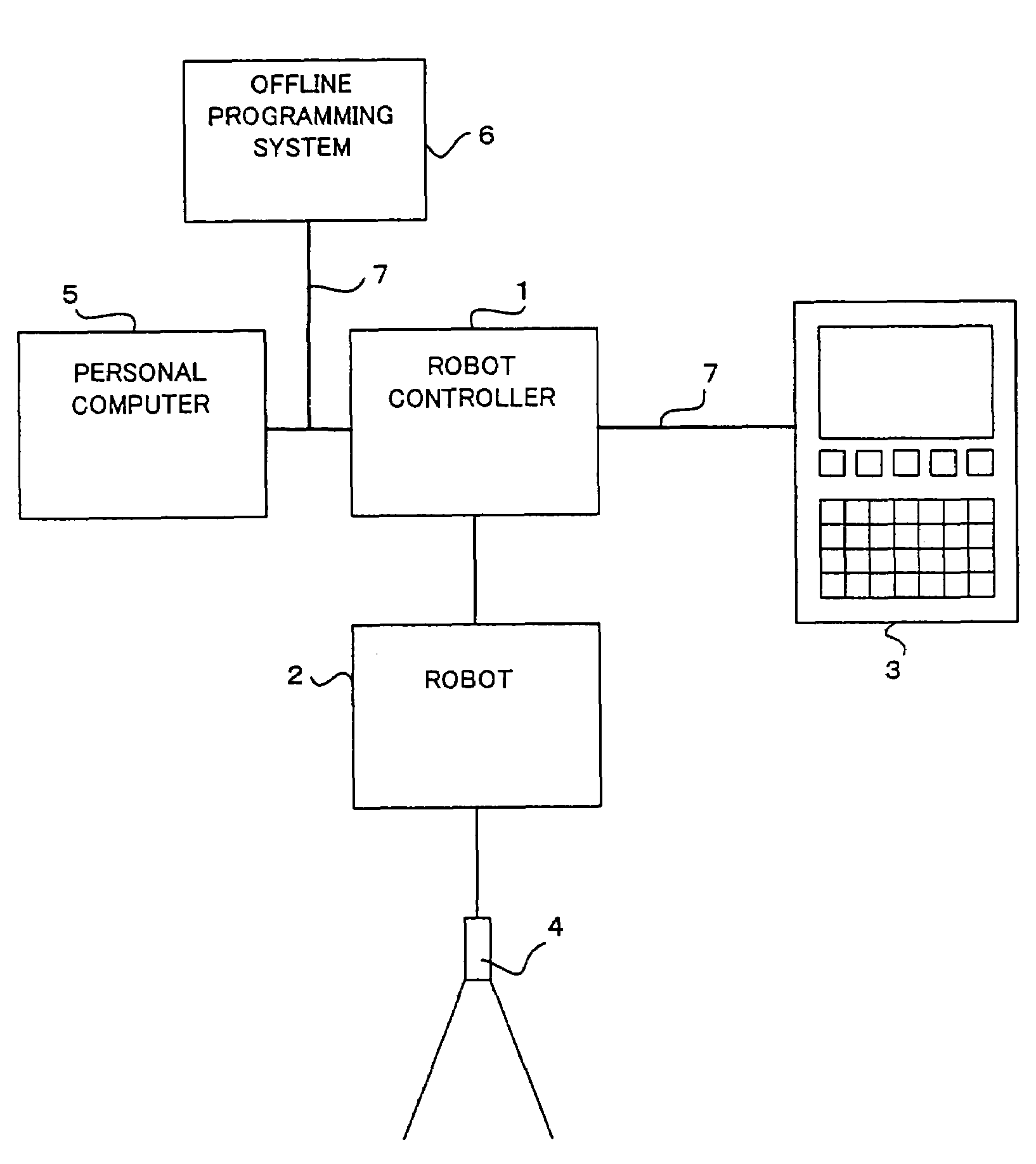
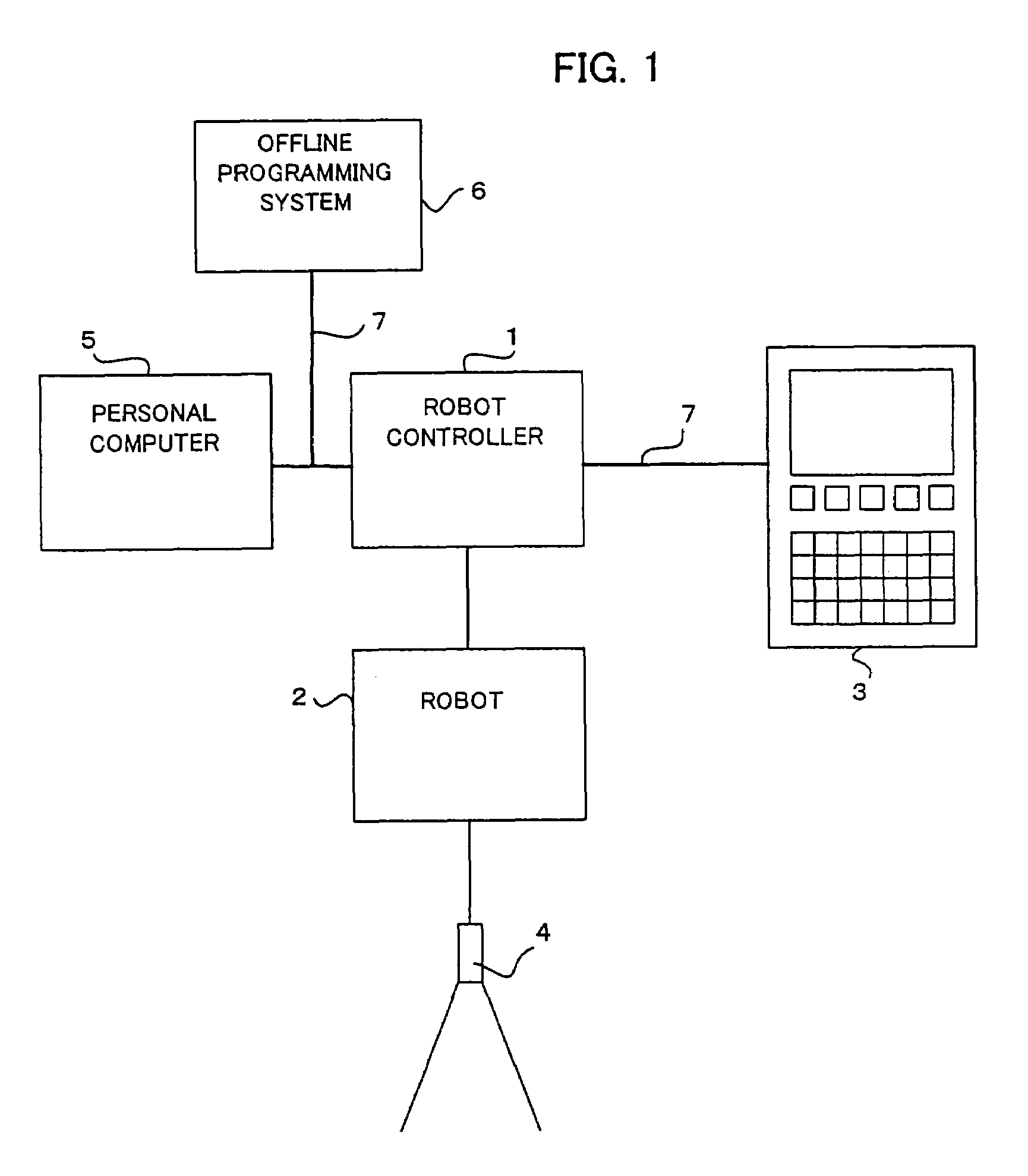
[0022]Referring to FIG. 1, a robot system according to an embodiment of this invention will be described.

[0023]The robot system includes a robot controller 1, and a robot 2 having robot arms, etc. serving as a movable portion of the robot. A visual sensor 4 such as a CCD camera is attached to a distal end of the robot arms. The robot controller 1 is connected to servomotors for driving the movable portion of the robot 2, and controls the servomotors to operate the robot. An information processing device (in this embodiment, a personal computer which will be referred to as PC) 5 and an offline programming system 6 are connected to the robot controller 1 via Ethernet (trademark) cables 7. A teaching pendant 3 is connected to the robot controller 1 via Ethernet (trademark) cables 7 or RS-422 cables.

[0024]In the case of Ethernet (trademark) cables being used for the connection, direct information exchange can be achieved between the teaching pendant 3, the PC 5, and the offline programming


PUM


Abstract

A taught position modification device easily correcting, in a short time, positions of taught points in a program prepared by an offline programming system. A workpiece image captured by a visual sensor and an image of a three-dimensional workpiece model having three characteristic points are displayed on a screen. Based on coordinate values of workpiece portions corresponding to the characteristic points which are specified in the workpiece image, the position and orientation of the model in a robot operating space are corrected, and also positions of taught points are corrected. When a tool end of a robot is positioned by jog feed to the operation position on a workpiece after being automatically moved to one of the corrected taught points, the taught point is modified based on the robot operating position detected at that time.

Description


Claims


Application Information

Patent Timeline
Owner FANUC LTD
Why Eureka
Try Eureka