Handheld rangefinder operable to determine hold-over ballistic information

a technology of hold-over ballistic information and hand-held rangefinders, which is applied in the field of hand-held rangefinders, can solve the problems of limited field of vision of devices, slope and elevation may affect the projectile path of bullets, and hunters are forced to manually perform hold-over calculations. to achieve the effect of facilitating accurate firearm us

Active Publication Date: 2011-12-20
BUSHNELL
View PDF107 Cites 41 Cited by
  • Summary
  • Abstract
  • Description
  • Claims
  • Application Information

AI Technical Summary

Benefits of technology

The present invention improves upon existing handheld range finders with range sensors and computing elements for accurately detecting bullet trajectory data. This allows users to quickly calculate the amount they can throw into their gun based on these data rather than manually calculating it themselves.

Problems solved by technology

The technical problem addressed in this patent is how to accurately measure the range from a gun to a target without requiring hunters to constantly check the accuracy of the range findings provided through traditional methods like holding up the weapon's trigger until they reach the desired target. This process requires constant attention and effort, making it difficult for hunters to achieve consistently high levels of precision.

Method used


Image

  • Handheld rangefinder operable to determine hold-over ballistic information
  • Handheld rangefinder operable to determine hold-over ballistic information
  • Handheld rangefinder operable to determine hold-over ballistic information

Examples


Embodiment Construction

[0025]The following detailed description of the invention references the accompanying drawings that illustrate specific embodiments in which the invention can be practiced. The embodiments are intended to describe aspects of the invention in sufficient detail to enable those skilled in the art to practice the invention. Other embodiments can be utilized and changes can be made without departing from the scope of the present invention. The following detailed description is, therefore, not to be taken in a limiting sense. The scope of the present invention is defined only by the appended claims, along with the full scope of equivalents to which such claims are entitled.

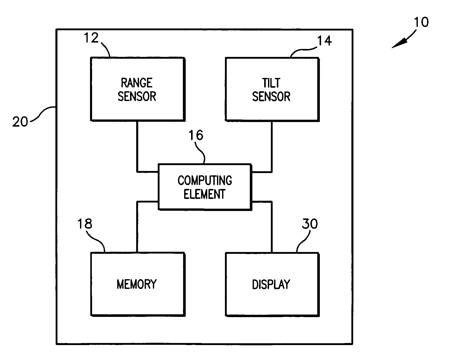
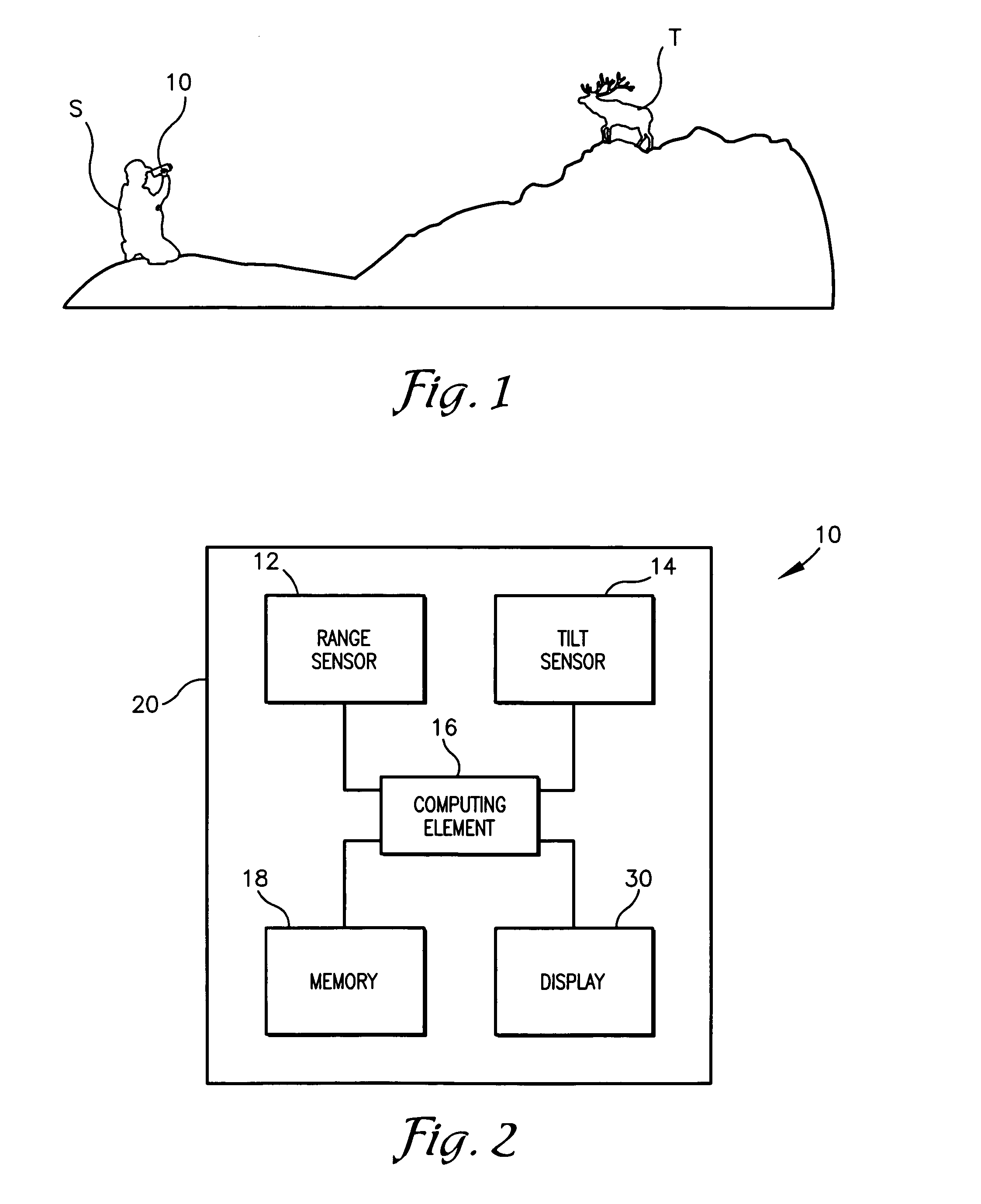
[0026]FIG. 1 illustrates a shooter taking aim at a target T with a rangefinder device 10, constructed in accordance with an embodiment of the present invention. The device 10 may be a small, portable, handheld device for use in determining a range to a target T, such as an animal, an angle to the target T, and ballistic in


PUM


Abstract

A handheld rangefinder device operable to determine ballistic hold-over information is disclosed. The rangefinder device generally includes a range sensor operable to determine a range to a target, a memory storing a database of ranges and corresponding hold-over values for a default sight-in distance, and a computing element, coupled with the range sensor and the memory. The computing element may calculate an adjusted hold-over value based on the range and an actual sight-in distance. Additionally, a tilt sensor may be included to provide information for calculating an angle-adjusted hold-over value. Such a configuration facilitates accurate firearm use by providing ranges and hold-over values without requiring time-consuming and manual user calculations.

Description


Claims


Application Information

Patent Timeline
Owner BUSHNELL
Why Eureka
Try Eureka