Tape system for framing

a technology of tape and frame, applied in the field of tape, can solve the problems of requiring a great deal of precision and accuracy in framing, and achieve the effect of accurate construction layou

Active Publication Date: 2012-07-24
MOONEY DARRELL R
View PDF20 Cites 13 Cited by
  • Summary
  • Abstract
  • Description
  • Claims
  • Application Information

AI Technical Summary

Benefits of technology

The present in this patented technology allows for precise placement of building components by creating detailed design drawings that include various types of markings such as labels indicating different colors used during construction. This makes it easier than ever before to lay down these designs correctly onto buildings without any errors caused due to incorrect placements.

Problems solved by technology

This patented technology helps make building frames faster by providing precise alignment between different materials without requiring complicated calculations. It also saves space when storing multiple parts together with no errors made during assembly process.

Method used


Image

  • Tape system for framing
  • Tape system for framing
  • Tape system for framing

Examples


Embodiment Construction

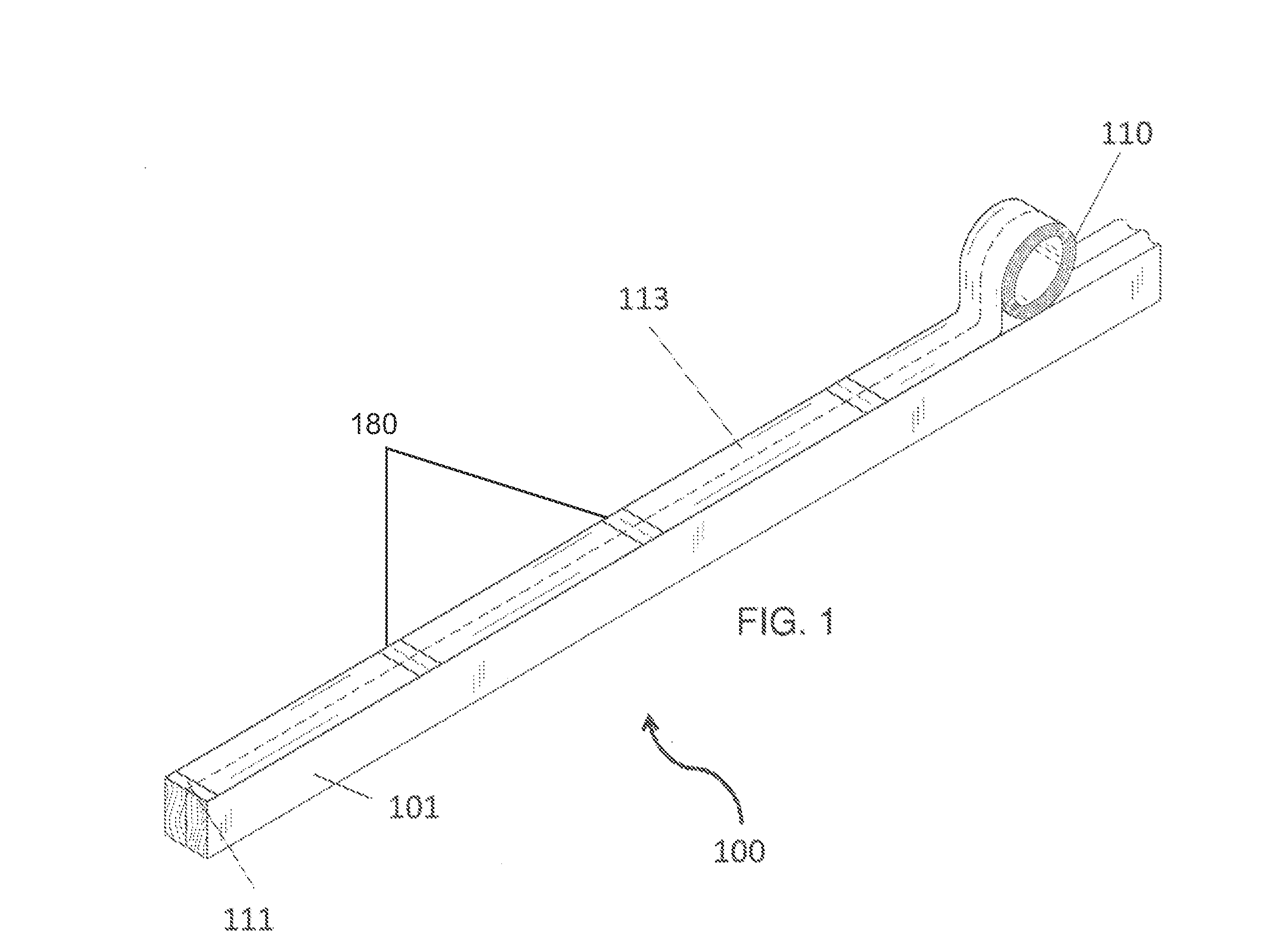
[0012]Referring now to FIGS. 1-5, the present invention features a tape system 100 for helping to ensure frame pieces 101 (e.g., wood, metal joist rafters, etc.) are assembled appropriately and exactly. The tape system 100 of the present invention comprises an elongated strand 110. The strand 110 is flexible to be moved into a roiled configuration (e.g., a roll, see FIG. 1). The strand 110 has a first end 111, a second end, a first edge (e.g., front edge), a second edge (e.g., back edge) a top surface 113, and a bottom surface, wherein an adhesive is disposed on the bottom surface. The first end 111 of the tape system 100 is free. As shown in FIG. 1, the tape system 100 can be laid across a frame piece 101.

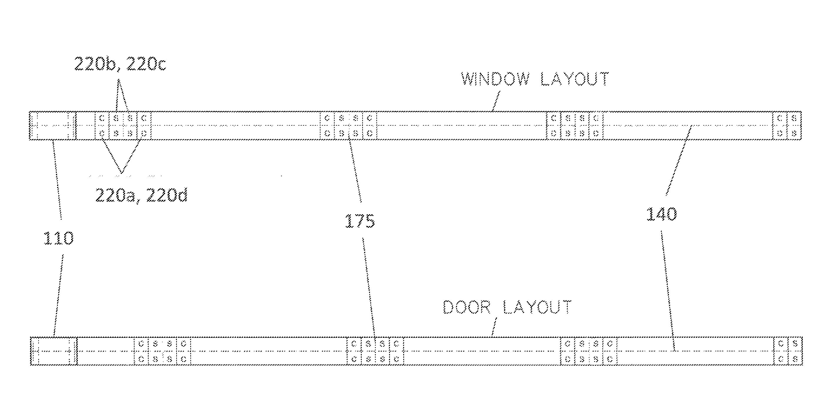
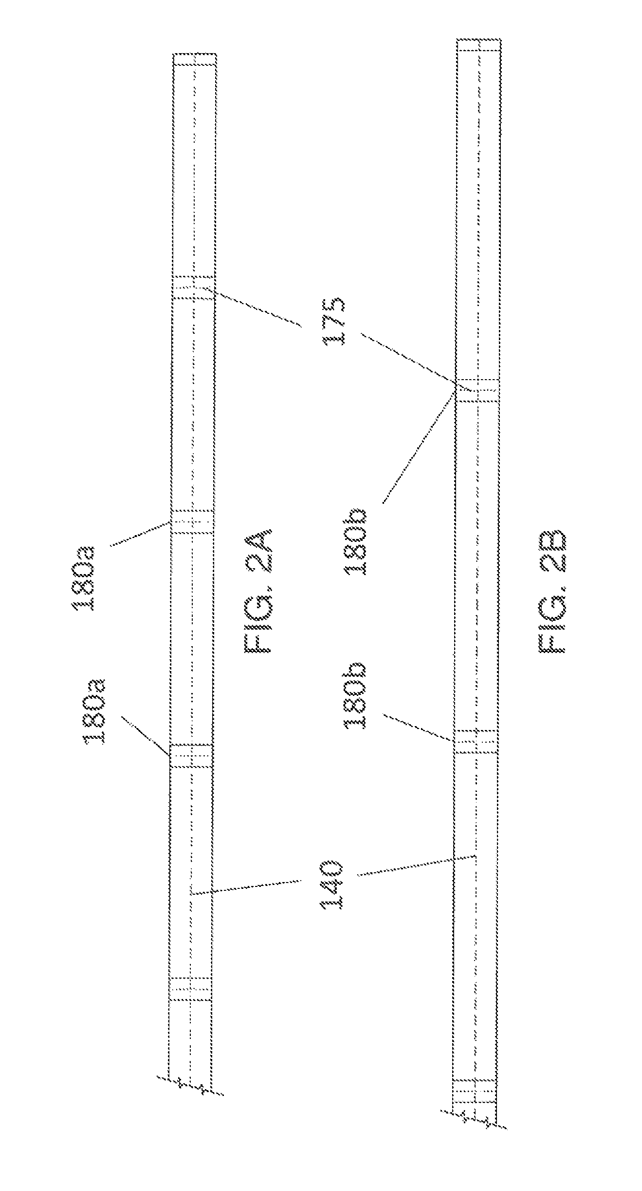
[0013]Disposed in the middle of the strand 110 running the length of the strand 110 (e.g., from the first end 111 to the second end) is a center line 140. Disposed across the strand 110 is a plurality of center markers 180. The center line 140 divides the center markers 180 into a to


PUM


Abstract

A tape system for obtaining accurate construction layouts featuring an elongated strand with an adhesive disposed on the bottom surface, the strand is flexible to allow movement between a rolled configuration and an elongated configuration; a center line disposed in a middle of the strand running from the first end to the second end of the strand; a plurality of center markers disposed along the strand spaced a certain distance apart, the center line divides each center marker into a top portion and a bottom portion, wherein both the top portion and the bottom portion of each center marker is labeled with a first letter, a second letter, a third letter, and a fourth letter; and perforations disposed in each center marker, the perforations being perpendicular to the center line and extending from the first edge of the strand to the second edge of the strand.

Description


Claims


Application Information

Patent Timeline
Owner MOONEY DARRELL R
Why Eureka
Try Eureka