Combined burner and lance apparatus for electric arc furnaces

a technology of electric arc furnaces and burners, which is applied in the direction of lighting and heating apparatus, furnace components, manufacturing converters, etc., can solve the problems of affecting the heating efficiency of the multi-function tool during the melting step, the level of raw solid metal piles in the furnace suddenly increases, and the heating efficiency of the burner is impaired. achieve the effect of improving energy efficiency and avoiding cold spots in the furna

Inactive Publication Date: 2012-12-18
LAIR LIQUIDE SA POUR LETUDE & LEXPLOITATION DES PROCEDES GEORGES CLAUDE
View PDF14 Cites 4 Cited by
  • Summary
  • Abstract
  • Description
  • Claims
  • Application Information

AI Technical Summary

Benefits of technology

The technical effect of this patented technology allows for more efficient use of fuel while reducing issues such as hot spot formation on refractory materials used inside industrial furnaces like steel production processes. By adjusting how much heat from burning off scraps or waste material helps prevent these areas that may get damaged due to temperature differences between different parts of the furniture being manufactured.

Problems solved by technology

In this patented technical problem addressed in the current literature relates to improving the performance of multiple function tools in electronic arc furnances while maintaining their reliability at high temperatures. Specifically, existing methods involve igniting fuel from both ends of the gun before the start of the next cycle, but they cannot always ensure optimal placement due to factors like temperature differences and oxidation rates. Additionally, previous attempts made either did not result in sufficient improvement or resulted in reduced thermal efficacy after prolonged exposure time periods.

Method used


Image

  • Combined burner and lance apparatus for electric arc furnaces
  • Combined burner and lance apparatus for electric arc furnaces
  • Combined burner and lance apparatus for electric arc furnaces

Examples


Embodiment Construction

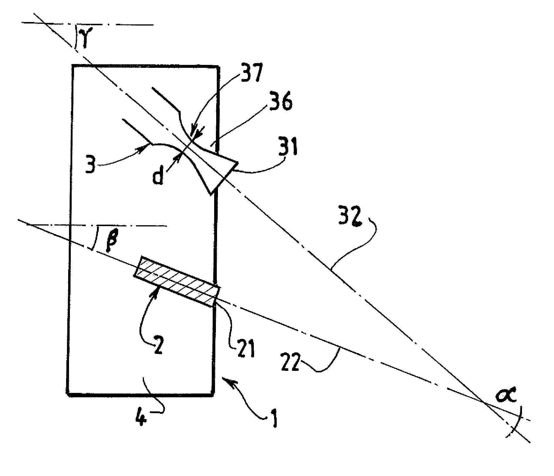
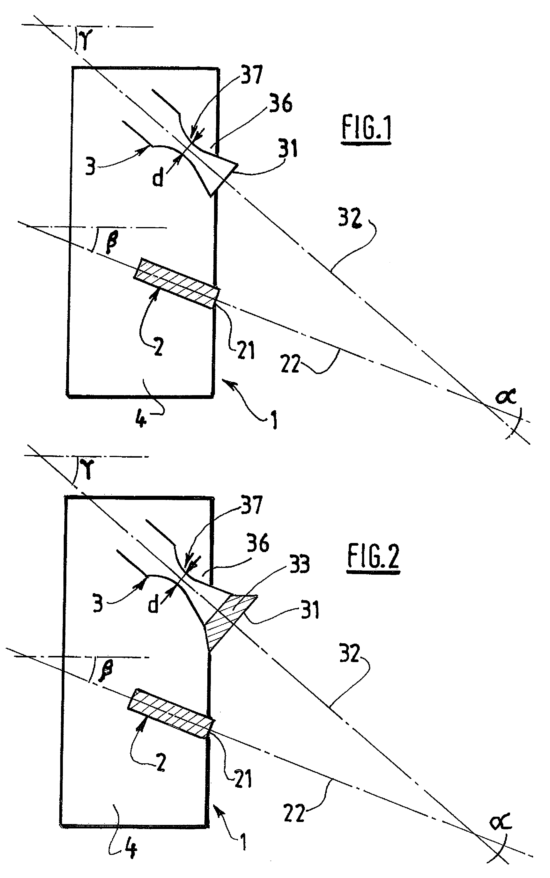
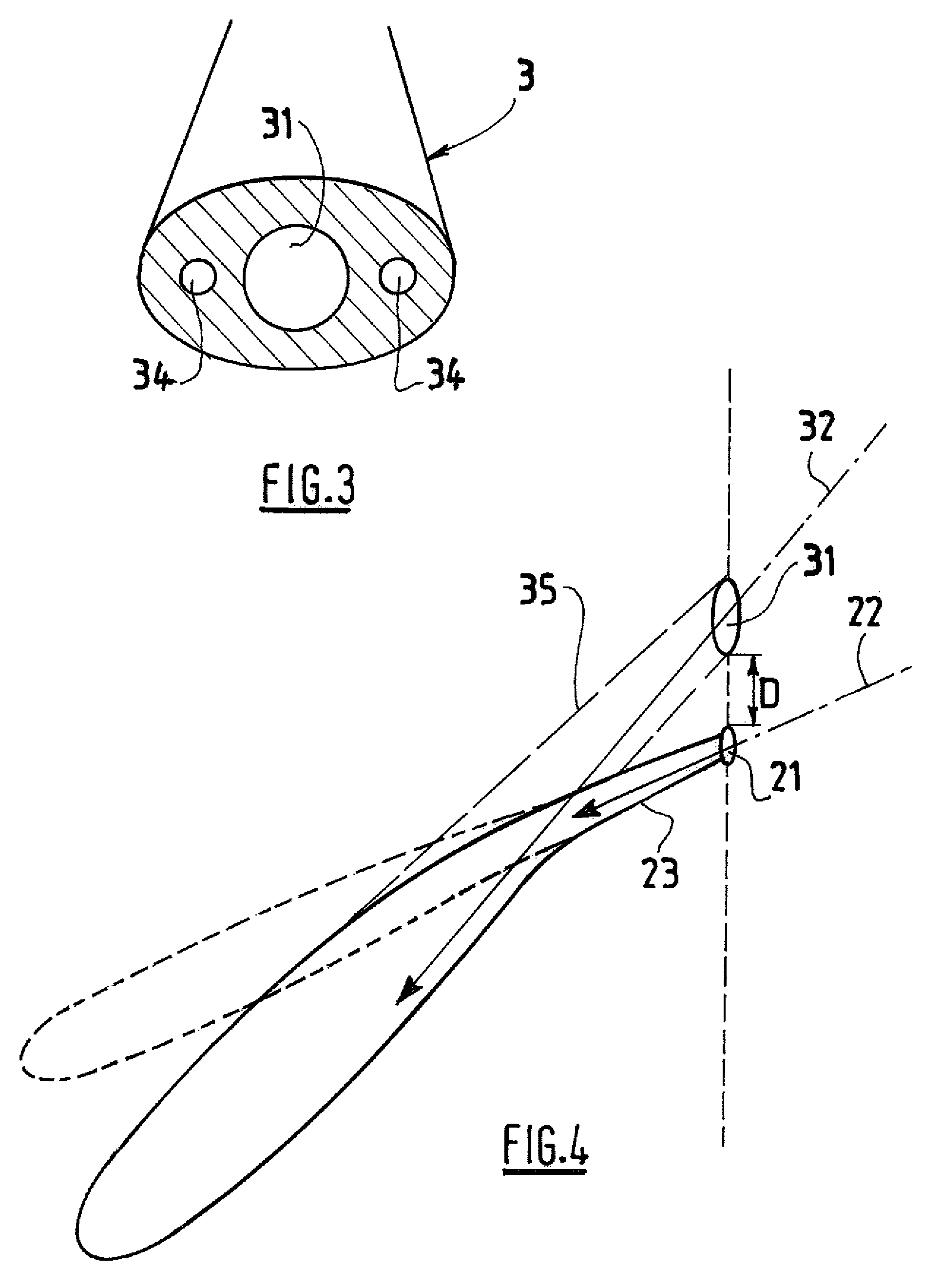
[0040]According to the present invention, the lance outlet opening 31 and the burner outlet 21 opening are not concentric. They are instead located at a distance D from one another, said distance D being at most 20 times the lance diameter and preferably no more than 10 times the diameter d of the sonic throat 37.

[0041]The lance axis 32 forms an angle α with the burner axis 22, said angle α being in the range from 10° to 40° and preferably from 15° to 30°. The angle α can, for example, be approximately 25°.

[0042]In this manner, the apparatus enables the direction of a flame produced by the burner to be deviated by fluid interaction with a gaseous jet produced or injected by the lance.

[0043]According to a preferred embodiment of the invention, the lance 3 is equipped with a divergent nozzle 33 downstream of the convergent-divergent nozzle, so that, when the burner 2 and the lance 3 are operated simultaneously, the jet injected by the lance covers a wider area of the circumference of the


PUM

PropertyMeasurementUnit
Timeaaaaaaaaaa
Angleaaaaaaaaaa
Angleaaaaaaaaaa

Abstract

Process and apparatus for melting raw material in an electric arc furnace using a flame of variable direction, the apparatus comprising a burner and a lance whereby the lance outlet opening and the burner outlet opening are not concentric and are located at a distance from one another, and whereby the lance axis forms an angle with the burner axis in the range from 10° to 40.

Description


Claims


Application Information

Patent Timeline
Owner LAIR LIQUIDE SA POUR LETUDE & LEXPLOITATION DES PROCEDES GEORGES CLAUDE
Why Eureka
Try Eureka