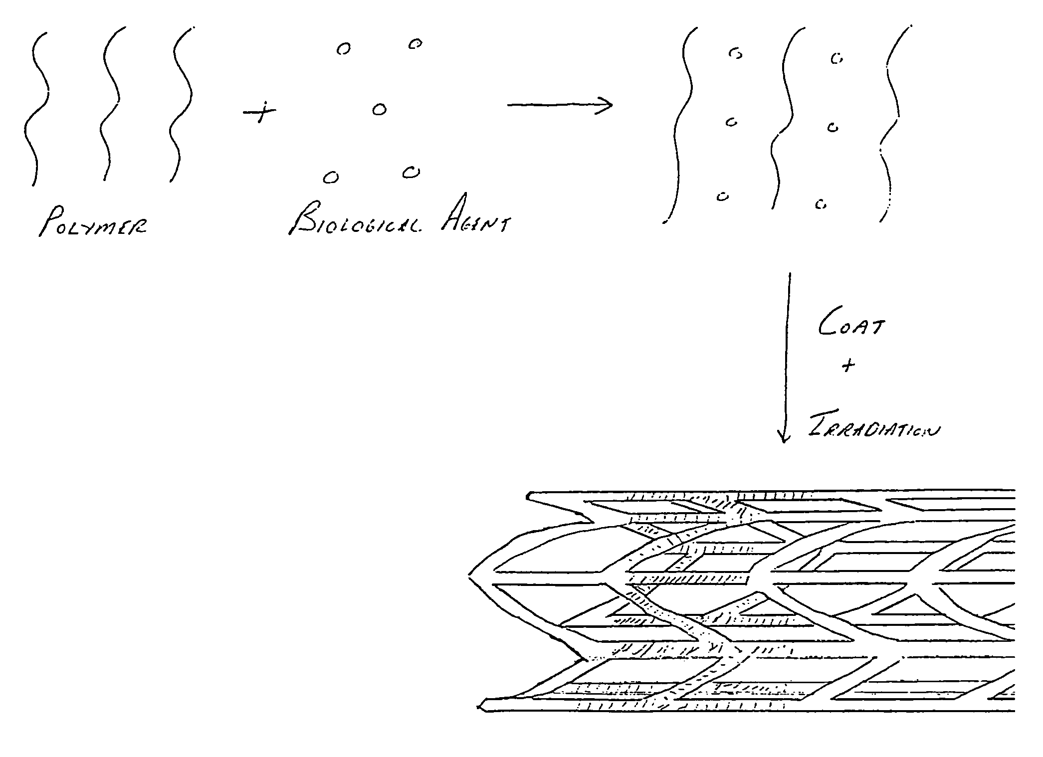
Irradiated stent coating
- Summary
- Abstract
- Description
- Claims
- Application Information
AI Technical Summary
Benefits of technology
Problems solved by technology
Method used
Image

Examples
Embodiment Construction
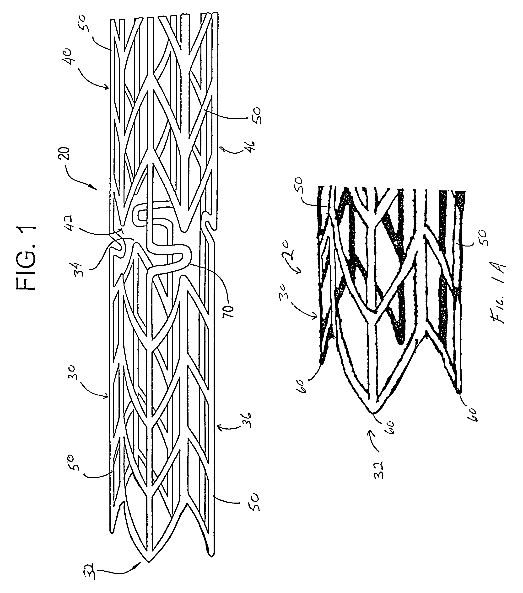
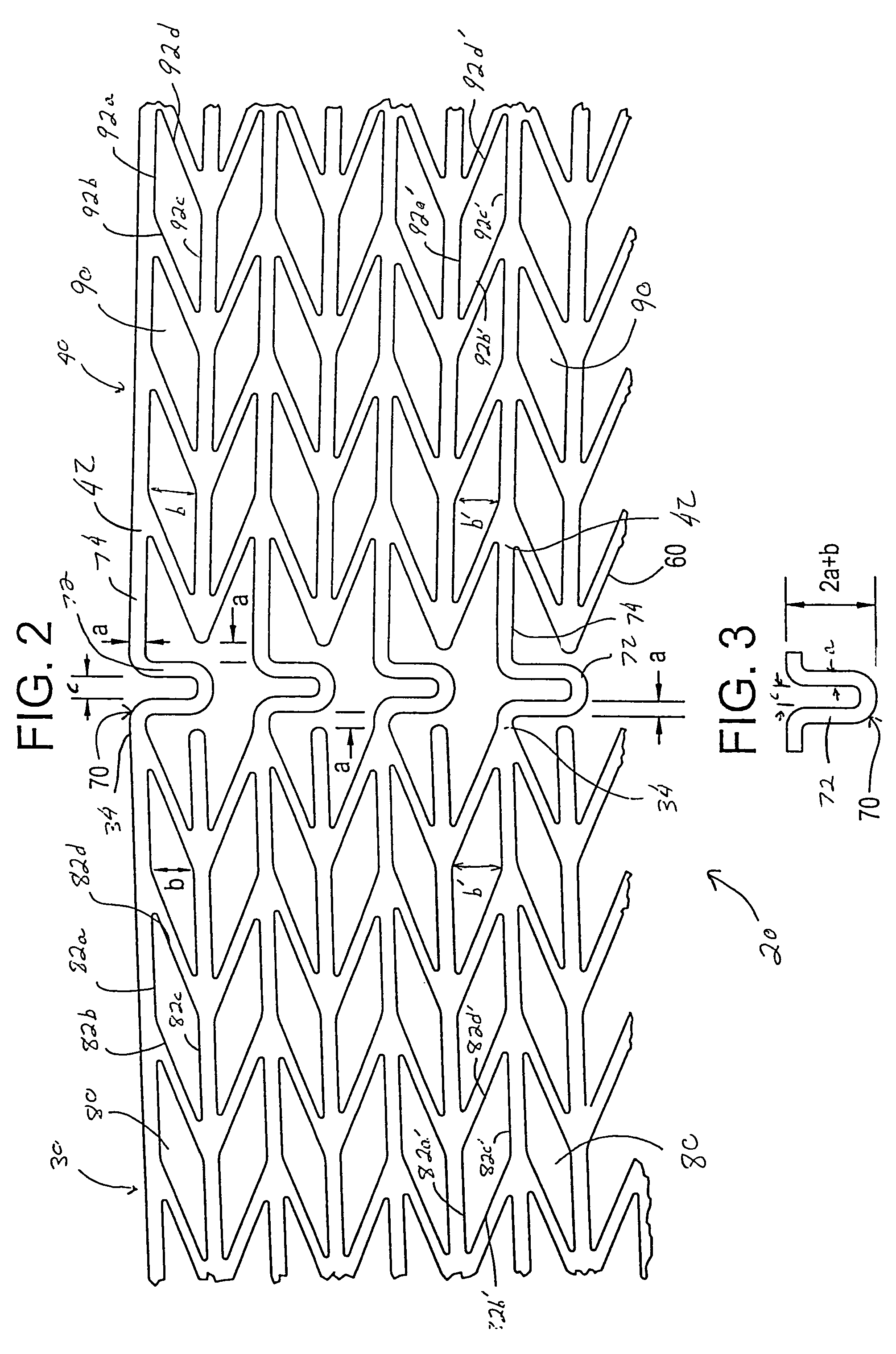
[0054]Referring now to the drawings wherein the showing is for the purpose of illustrating preferred embodiments of the invention only and not for the purpose of limiting the same, FIGS. 1-8 disclose a stent for a body passageway. The apparatus and structures of the present invention may be utilized not only in connection with an expandable stent for at least partially expanding occluded segments of a body passageway, but also for additional uses. For example, the expandable stent may be used for, but not limited to, such purposes as 1) a supportive stent placement within a blocked vasculature opened by transluminal recanalization, which are likely to collapse in the absence of an internal support; 2) forming a catheter passage through mediastinal and / or other veins occluded by inoperable cancers; 3) reinforcement of catheter created intrahepatic communications between portal and / or hepatic veins in patients suffering from portal hypertension; 4) supportive stent placement of narro
PUM
| Property | Measurement | Unit |
|---|---|---|
| Length | aaaaa | aaaaa |
| Diameter | aaaaa | aaaaa |
| Hydrophobicity | aaaaa | aaaaa |
Abstract
Description
Claims
Application Information
 - R&D Engineer
- R&D Manager
- IP Professional
- Industry Leading Data Capabilities
- Powerful AI technology
- Patent DNA Extraction
Browse by: Latest US Patents, China's latest patents, Technical Efficacy Thesaurus, Application Domain, Technology Topic.
© 2024 PatSnap. All rights reserved.Legal|Privacy policy|Modern Slavery Act Transparency Statement|Sitemap