Aircraft having circular body and blades

a technology of aircraft and blades, applied in the direction of propellers, emergency apparatus, transportation and packaging, etc., can solve the problems of craft rolling or flipping on contact, requiring a high horsepower requirement, and the drive system is at a mechanical disadvantage, so as to avoid the dangers of mechanical failure, avoid mechanical failure, and maneuverability.

Active Publication Date: 2017-01-31
DRONEXUS AERO LLC
View PDF15 Cites 14 Cited by
  • Summary
  • Abstract
  • Description
  • Claims
  • Application Information

AI Technical Summary

Benefits of technology

The technical effect of this patented technology for creating better-stable or more manageably movable airplanes by providing them with improved stability without being affected from any other factors like machine failures.

Problems solved by technology

This patented technical problem addressed by the present inventors relates to improving the stability and control over flight vehicles during operation due to their long-term use of hydraulics and gears. Current methods involve adding weight to stabilizing these components but they also increase drag when moving through them.

Method used


Image

  • Aircraft having circular body and blades
  • Aircraft having circular body and blades
  • Aircraft having circular body and blades

Examples


Embodiment Construction

[0020]In describing a preferred embodiment of the invention illustrated in the drawings, specific terminology will be resorted to for the sake of clarity. However, the invention is not intended to be limited to the specific terms so selected, and it is to be understood that each specific term includes all technical equivalents that operate in similar manner to accomplish a similar purpose. Several preferred embodiments of the invention are described for illustrative purposes, it being understood that the invention may be embodied in other forms not specifically shown in the drawings.

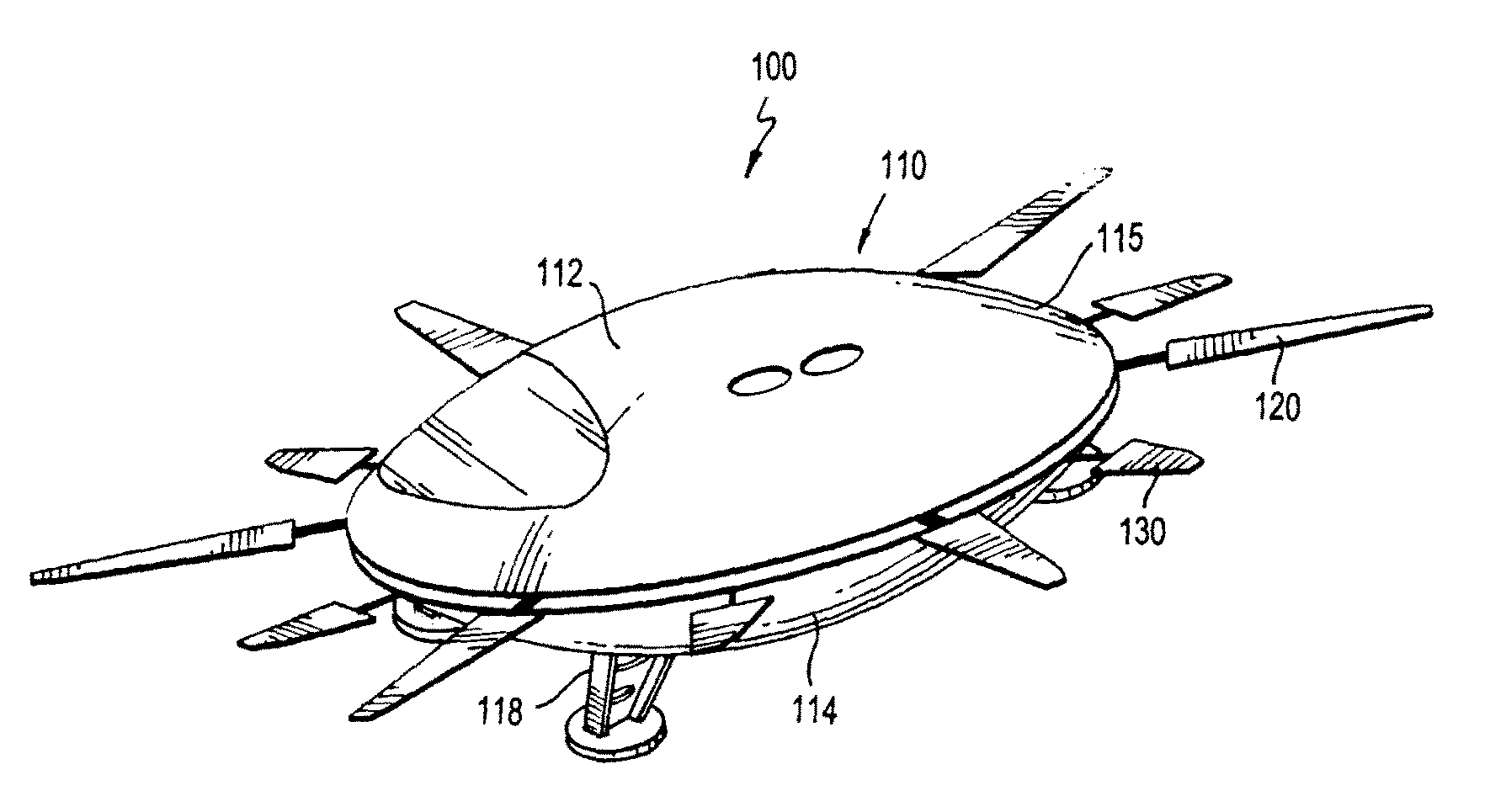
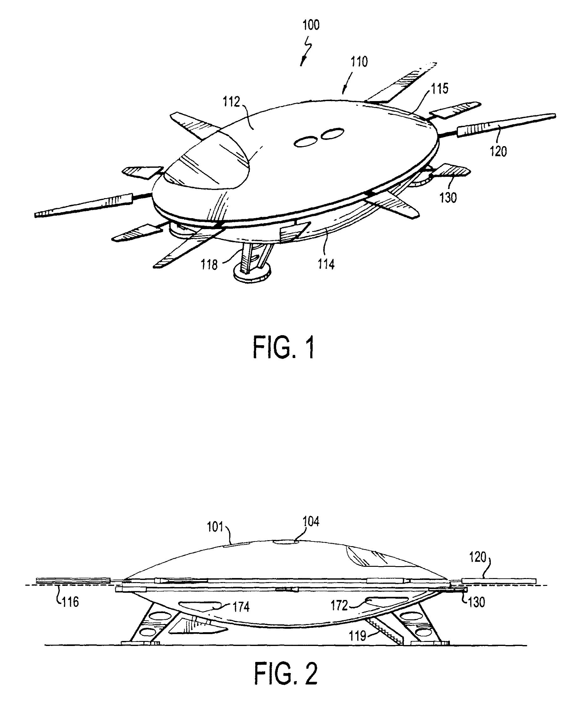
[0021]Turning to the drawings, FIGS. 1-2 shows an aircraft 100 in accordance with one preferred embodiment of the invention. The aircraft 100 includes a main housing or body 110, lift blades 120 and counter-rotation (or anti-torque) airfoil blades 130. The main body 110 has an upper body portion 112, a lower body portion 114, landing gear 118, and other usual features such as a cockpit, seating and windows.


PUM


Abstract

An aircraft has a main body with a circular shape and a circular outer periphery. One or more rotor blades extend substantially horizontally outward from the main body at or about the circular outer periphery. In addition, one or more counter-rotation blades extend substantially horizontally outward from said main body at or about the circular outer periphery, but vertically offset from the main rotor blades. The main rotor blades are connected to a first annular gear that rotates in a first direction and the counter-rotation blades rotate are connected to a second annular gear that rotates in a second direction that is opposite the first direction for anti-torque. Planetary gears simultaneously drive the first and second annular gear at about the same speed.

Description


Claims


Application Information

Patent Timeline
Owner DRONEXUS AERO LLC
Why Eureka
Try Eureka