Cordless LED headlight and control thereof
- Summary
- Abstract
- Description
- Claims
- Application Information
AI Technical Summary
Benefits of technology
Problems solved by technology
Method used
Image

Examples
second embodiment
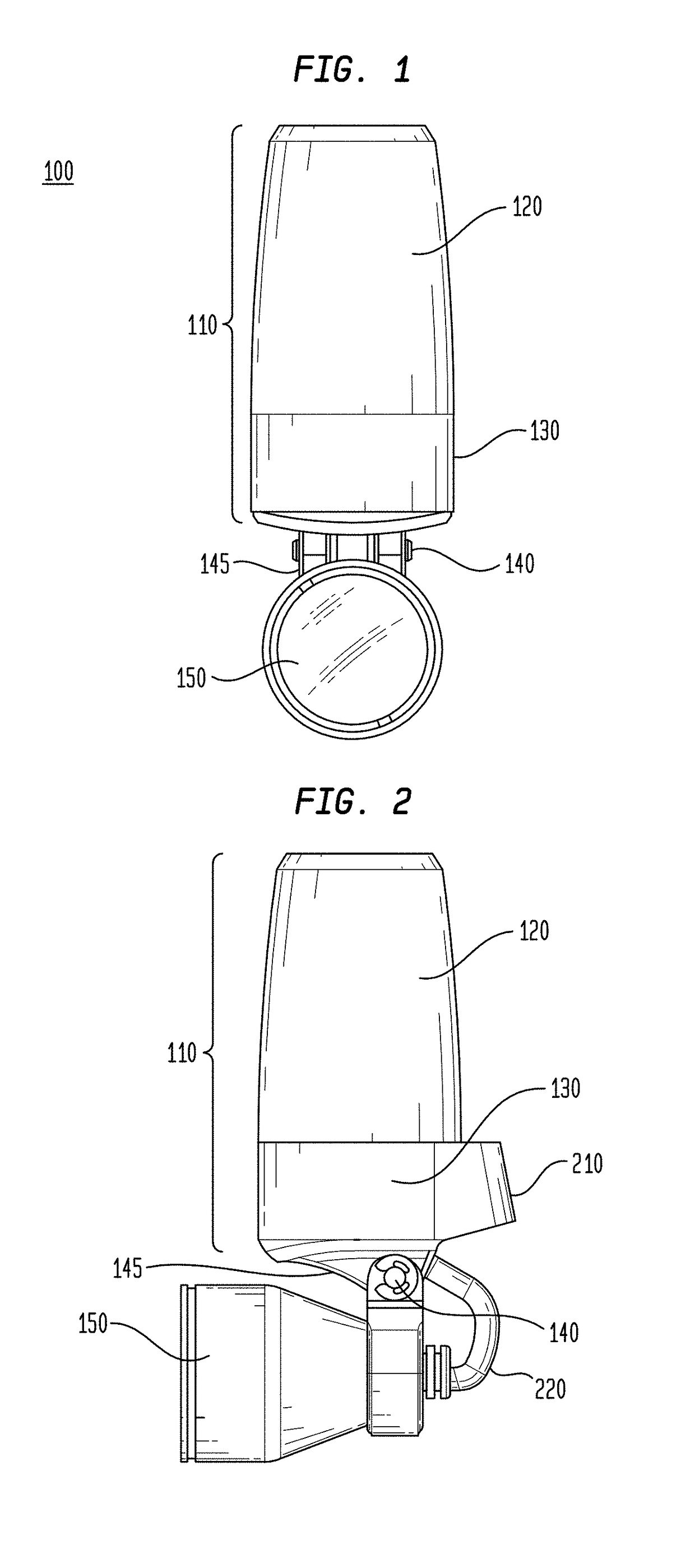
[0082]FIG. 8A illustrates a perspective view of the cordless headlight assembly in accordance with the principles of the invention.
[0083]In the illustrated embodiment shown in FIG. 8A, battery pod 120 engages a housing or connector element 130, as previously described. Battery pod 120 may engage housing or connector element 130 by means of a screw thread attachment, a slip joint attachment, a bayonet attachment, etc., as previously discussed.
[0084]FIG. 8B illustrates a top view of the lower portion of the battery pod in accordance with the second embodiment of the cordless headlight assembly shown in FIG. 8A.
[0085]In this illustrated second embodiment, an inner positive ring or center contact 640 (as previously discussed) and an outer negative ring 825 are shown. Positive ring or center contact 640 engages a positive terminal of a battery element (not shown but similar to battery 530 shown in FIG. 5) and negative ring 825 engages a negative terminal of the battery element. In this c...
third embodiment
[0092]FIG. 10A illustrates a side view of a cordless headlight assembly in accordance with the principles of the invention.
[0093]In the illustrated embodiment, which is similar to the embodiment shown in FIG. 8A, a translucent window 1010 is created in metal ring 835 (or connector 130). Translucent window 1010 allows for the output of a light (e.g., infra-red, visible), an audio signal and / or an radio frequency (RF) signal) that may be used to provide for a contactless switching mechanism. U.S. Pat. No. 8,851,709, which is assigned to the owner of the instant application and incorporated by reference herein.
[0094]FIG. 10B illustrates a front view of a cordless headlight assembly shown in FIG. 10A showing the translucent window 1010.
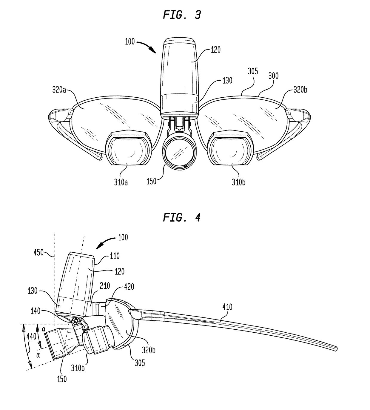
[0095]FIG. 10C illustrates a perspective view of the cordless headlight assembly shown in FIG. 10A, showing an axis 1030 of the outputted light (Infra-Red (IR), visible and / or ultra-violet (UV), audio and / or RF signals and an axis 1020 of headlamp assembl...
fourth embodiment
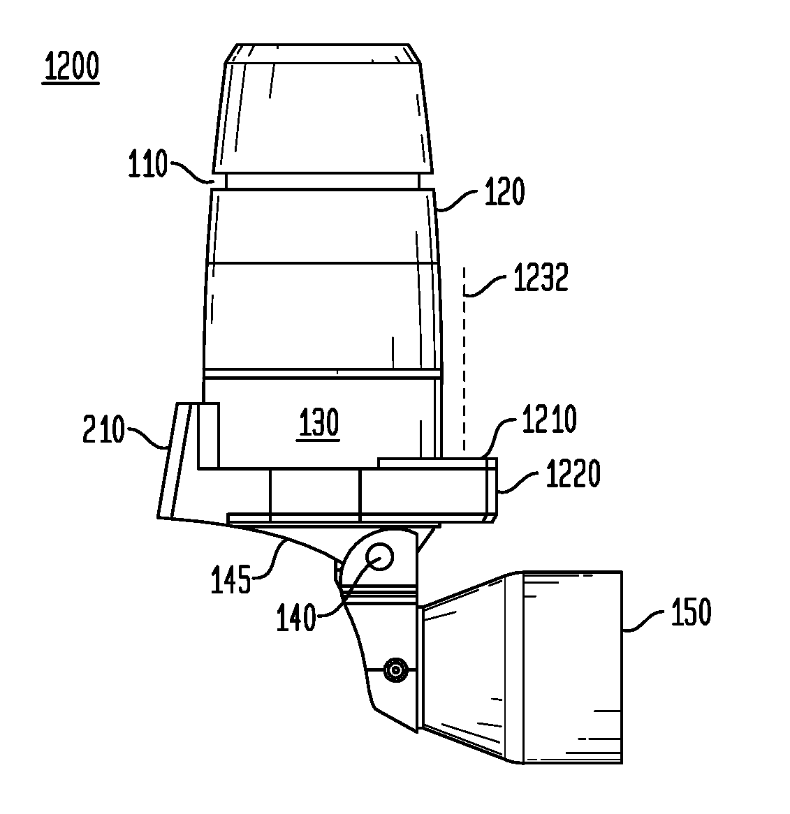
[0117]In this illustrated embodiment, the projection or ledge 1695 containing the sensing unit 1210 may be rotated about a rotary hinge 1910 (see FIG. 19) so as to position the sensing unit 1210 in a desired position. Also shown is an axis 1832 of the outputted light (Infra-Red (IR), visible and / or ultra-violet (UV), audio and / or RF signals transmitted by transmitter 1212. FIG. 20 illustrates a top view of a cordless headlight assembly in accordance with the invention. In this illustrate case, the transmitter 1212 and the receiver 1214 are shown in a position similar to that of FIG. 17. However, it would be recognized that in this embodiment, the orientation of the transmitter 1212 and the receiver 1214 may be rotated from one of transmission of a single substantially parallel to an axis of the battery pod assembly to one of substantially perpendicular to an axis of the battery pod assembly.
[0118]Although not shown, it would be recognized that the rotatable hinge 1910 may include a ...
PUM
 Abstract
Description
Claims
Application Information
 - R&D Engineer
- R&D Manager
- IP Professional
- Industry Leading Data Capabilities
- Powerful AI technology
- Patent DNA Extraction
Browse by: Latest US Patents, China's latest patents, Technical Efficacy Thesaurus, Application Domain, Technology Topic.
© 2024 PatSnap. All rights reserved.Legal|Privacy policy|Modern Slavery Act Transparency Statement|Sitemap