Handcart propelling mechanism of single phase vacuum circuit breaker in electric railway user

A technology for vacuum circuit breakers and electrified railways, applied to electrical components, switchgear, pull-out switchgear, etc., can solve the problems of poor transmission stability, large mechanism volume, and inconvenient use, and achieve stable transmission, small size, Labor-saving effect

Inactive Publication Date: 2007-10-03
南京赛彤铁路电气化有限公司
View PDF0 Cites 0 Cited by
  • Summary
  • Abstract
  • Description
  • Claims
  • Application Information

AI Technical Summary

Benefits of technology

This new design improves on existing designs by making them smaller while still being effective at transmitting power effectively compared to older methods like levers or hydraulic systems that were previously used for this purpose. Its main technical effect includes improved reliability over longer periods without requiring frequent maintenance due to its compactness and sturdy structure. Additionally, there are fewer moving mechanical elements such as pawls and cams, which makes their assembly process faster and easier. Overall, these improvements improve overall performance and reduce costs associated with current technologies

Problems solved by technology

Technological Problems with current methods for moving an electric railway system's load carrying switches include instability during operation due to insufficient movement or reduced lifting capacity caused by excessive bouncing between different parts such as the carriage body and its connected linkages when pulling on the handles that activate them through levers.

Method used


Image

  • Handcart propelling mechanism of single phase vacuum circuit breaker in electric railway user
  • Handcart propelling mechanism of single phase vacuum circuit breaker in electric railway user
  • Handcart propelling mechanism of single phase vacuum circuit breaker in electric railway user

Examples


Embodiment Construction

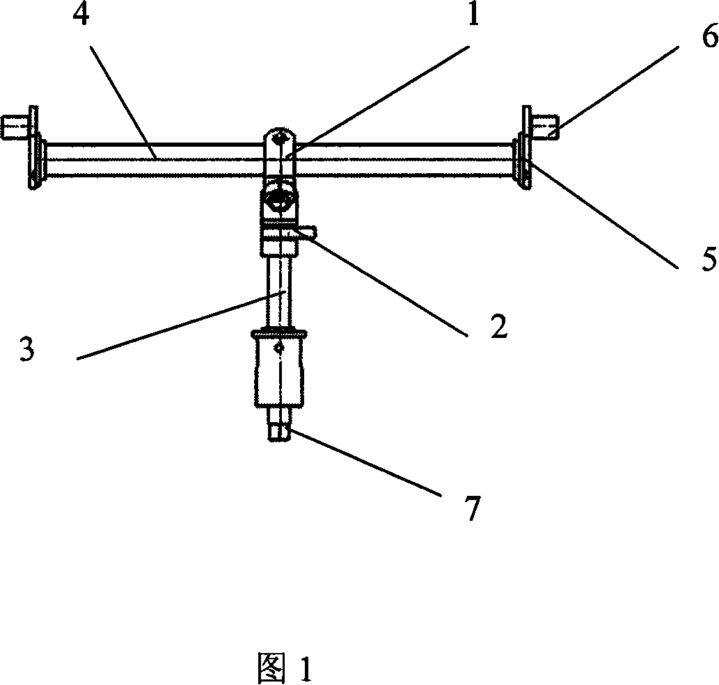
[0019] A handcart propulsion mechanism for an indoor single-phase vacuum circuit breaker for electrified railway users according to the present invention includes a transmission shaft 3, a bearing 2, a crank arm 1, a main shaft 4, an end plate 5, a roller 6 and a hexagonal end 7. The transmission shaft 3 is fixed under the handcart of the circuit breaker through the bearing 2 and the bushing. One end of the transmission shaft 3 is a hexagonal end 7 that matches the sleeve rocker arm. The other end of the transmission shaft 3 is composed of two crank arms 1. The ten bytes are connected to spindle 4. Rotate the hexagonal end 7 with the rocker arm to generate torque, so that the transmission shaft 3 rotates, and transmits to the main shaft 4 through the ten bytes formed by the two crank arms 1, so that the main shaft 4 rotates thereupon. The main shaft 4 is fixed on the lower part of the handcart of the circuit breaker and close to the track through bearings. Both ends of the main s


PUM


Abstract

An advancing mechanism of single phase vacuum breaker handcart used on electronic rail way is prepared as fixing a driving shaft at bottom of said handcart through bearing, setting hexagon end on one end of said shaft and crosshead on another end of said shaft for driving master shaft to rotate when said shaft is rotated, fixing master shaft at bottom of said handcart near to rail, setting end plates with rollers at two ends of master shaft and rollers in guard block of body frame on said handcart for driving said handcart to move back and forward when master shaft is rotated.

Description


Claims


Application Information

Patent Timeline
Owner 南京赛彤铁路电气化有限公司
Why Eureka
Try Eureka