Device for expanding thermal shrinkage tube

A technology of expansion device and heat-shrinkable tube, which is applied to tubular objects, other household appliances, household appliances, etc., can solve the problems of short service life, poor cooling effect, and low expansion efficiency of sizing tubes, so as to improve service life, Improve cooling effect and reduce friction

Active Publication Date: 2008-12-24
CHANGYUAN ELECTRONICS DONGGUAN +3
View PDF0 Cites 15 Cited by
  • Summary
  • Abstract
  • Description
  • Claims
  • Application Information

AI Technical Summary

Benefits of technology

This technology allows for better cooling performance with less energy consumption compared to traditional methods like spray coating or immersion quenching techniques that use liquid nitrogen (LN2) instead of gaseous ammonia. By pumping water from an openings inside the sized pipes through holes near them, it becomes more effective than other ways of doing this because there are fewer steps needed per unit time when making sure they don't get too much contamination during production. Additionally, these new technologies allow for faster thermal processes while also reducing wear caused by contact between the hot tubular material and its walls. Overall, this innovative method provides improved cooling capabilities without increasing costs associated with current methods such as spray coatings or immersequensers.

Problems solved by technology

The technical problem addressed by this patented technology relating to expanding thermally shaped pipings involves improving their ability to absorb moisture during use without losing its strength due to insoluble particles that may get inside from outside sources like rainwater when used with an automobile's brakes system.

Method used


Image

  • Device for expanding thermal shrinkage tube

Examples


Embodiment Construction

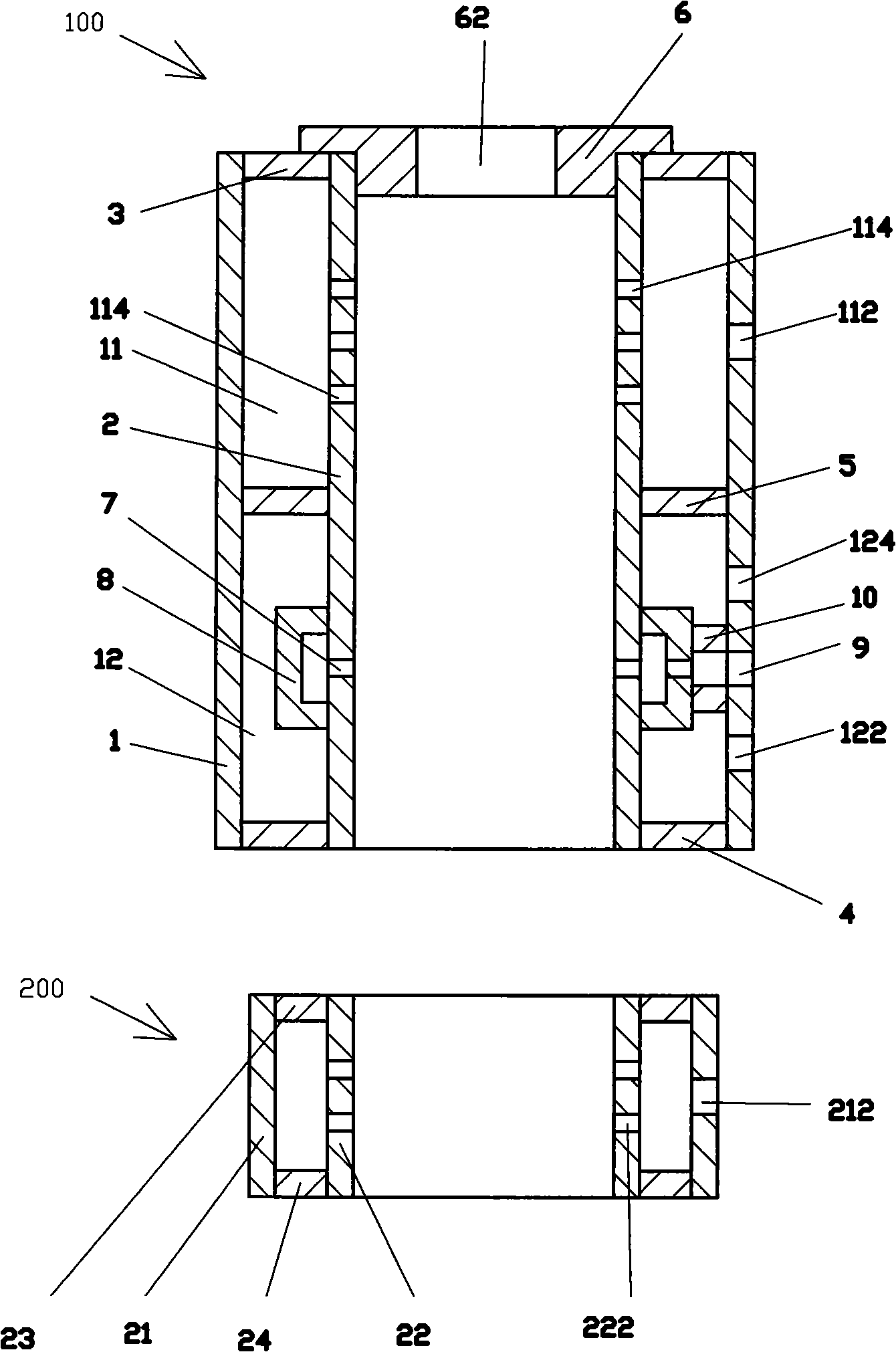
[0017] see figure 1 , a heat shrink tube expansion device, which includes an expansion mold 100, a water absorber 200.

[0018] The expansion die 100 includes a jacket 1, a fixed diameter pipe 2, a front sealing plate 3, a rear sealing plate 4, a partition 5, a die mouth 6, several water inlet holes 7, a water inlet jacket 8, a fixed diameter Pipe water inlet 9, a connecting pipe 10.

[0019] The jacket 1 is a body with two ends open.

[0020] The sizing pipe 2 is a straight cylinder made of bronze or stainless steel with two ends open. The sizing pipe 2 is installed inside the casing 1 . The inner diameter of the sizing tube 2 is the same as or slightly larger than the outer diameter of the expanded heat-shrinkable tube (not shown).

[0021] The front sealing plate 3 is fixedly installed between the outer cover 1 and the front end of the sizing tube 2 (that is, the end where the heat-shrinkable tube to be expanded (not shown) enters the sizing tube 2), and the outer cover 1


PUM


Abstract

The invention discloses a thermal shrinkage pipe expansion device which comprises an expansion die. The expansion die comprises an outer casing and a sizing tube. The sizing tube is arranged in the outer casing. The space between the outer casing and the sizing tube is separated into a vacuum chamber and a cooling chamber. The outer casing on the cooling chamber is provided with at least one water inlet and at least one water outlet. The expansion die also comprises a plurality of water inlet holes which are arranged on the sizing tube of the cooling chamber. Cooled water can enter the inside of the sizing tube through the water inlet holes. The thermal shrinkage pipe expansion device of the invention has the advantages of good cooling effect, light friction between the thermal shrinkage pipe and the sizing tube, high expansion efficiency, fast speed, long service life of the sizing tube and small axial shrinkage rate of products.

Description


Claims


Application Information

Patent Timeline
Owner CHANGYUAN ELECTRONICS DONGGUAN
Why Eureka
Try Eureka