Smelting furnance of copper tube
A copper tube and smelting furnace technology, applied in the copper tube smelting furnace, can be used in the field of smelting furnaces for continuous casting of copper tubes, and can solve the problems of poor quality of copper tube blanks, limitations of continuous casting tractors, and comprehensive costs Advanced problems, to achieve rationalization, improve quality, reduce energy consumption
- Summary
- Abstract
- Description
- Claims
- Application Information
AI Technical Summary
Problems solved by technology
Method used
Image

Examples
Embodiment 1
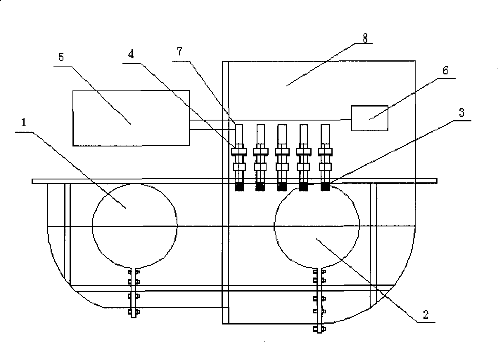
[0014] like figure 1 As shown, the copper tube smelting furnace of the present invention includes a melting furnace 1, a holding furnace 2, an upper drawing mold 3, a crystallizer 4, a traction motor 6, a speed regulating device 5, and a cooling water system and an electrical system that are conventionally provided, All are installed on the body 8 according to the conventional technology, the melting furnace 1 and the holding furnace 2 are connected in parallel, and the melting furnace 1 is smaller than the holding furnace 2; 10 crystallizers 4 are installed in two rows on the body 8, 5 in each row, crystallization The lower end of the device 4 is connected with the upper drawing mold 3, and the upper end is connected with the traction motor 6 through the copper tube 7 extracted from the crystallizer 4. The speed regulating device 5 is in contact with the copper tube 7 and connected with the traction motor 6 . like figure 2 As shown, the speed regulating device 5 includes a nu
Embodiment 2
[0016] The structure of the copper tube smelting furnace of this embodiment differs from that of Embodiment 1 in that nine crystallizers 4 are installed in two rows on the body, with five in one row and four in the other.
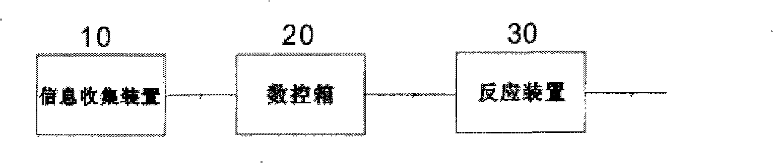
[0017] When the copper tube smelting furnace of each of the above embodiments is working, the treated electrolytic copper plate is added to the melting furnace 1 for melting, and after the molten copper is left to stand in the holding furnace 2, it enters the crystallizer 4 through the upper drawing mold 3 to crystallize out Copper tube, the copper tube 7 of crystallization is pulled out by traction motor 6 again. In this production process, the choice of traction speed is directly related to the output and quality of products. For this reason, the copper tube smelting furnace is equipped with a speed regulating device 5, through which the speed of the traction motor 6 is adjusted to realize the rationalization and normalization of the traction speed, and the
PUM
 Abstract
Description
Claims
Application Information
 - R&D Engineer
- R&D Manager
- IP Professional
- Industry Leading Data Capabilities
- Powerful AI technology
- Patent DNA Extraction
Browse by: Latest US Patents, China's latest patents, Technical Efficacy Thesaurus, Application Domain, Technology Topic.
© 2024 PatSnap. All rights reserved.Legal|Privacy policy|Modern Slavery Act Transparency Statement|Sitemap