Test method for step response performance of phase-locked loop system

A step-response, phase-loop system technology, applied in the field of phase-locked loop systems, can solve problems such as inconvenient extraction, measurement errors, and inability to obtain measurement values, and achieve the effects of convenient operation and improved measurement accuracy.

Inactive Publication Date: 2009-08-05
北京芯汇中秀电子技术有限公司
View PDF0 Cites 9 Cited by
  • Summary
  • Abstract
  • Description
  • Claims
  • Application Information

AI Technical Summary

Benefits of technology

The technical effect of this new technology described by the current inventor testing an electronic device's power supply can be that its output voltage signals are tested for both excessive or short-circuiting without affecting their stability. This eliminates any extra noise introduced during these measurements while improving the overall performance of the circuitry being measured accurately.

Problems solved by technology

This patented describes various techniques related to improving the accuracy and efficiency of phase-lock circuits used in communication devices like phased Locked Loops (PLoL). These improvements include reducing variations caused by temperature fluctuations and instability sources, increasing reliance on digital processing technology, enabling more precise measurements through analog methods, integrating multiple functions into single chip designs, controller design, and implementing advanced test procedures. Additionally, these technologies can be applied across diverse industries depending upon their specific needs.

Method used


Image

  • Test method for step response performance of phase-locked loop system
  • Test method for step response performance of phase-locked loop system

Examples


Embodiment Construction

[0024] The implementation of the present invention will be described in detail below in conjunction with the accompanying drawings and examples, so as to fully understand and implement the process of how to apply technical means to solve technical problems and achieve technical effects in the present invention.
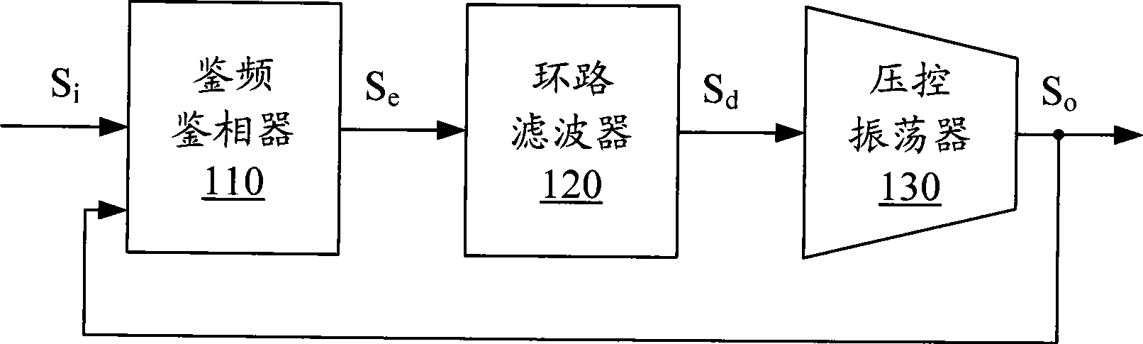
[0025] The basic idea of ​​the present invention is to indirectly measure the system overshoot and loop stabilization time according to the frequency change of the system output voltage signal. Since the oscillation frequency of the voltage-controlled oscillator 30, that is, the frequency of the system output voltage signal follows the control voltage S d The change of the change, and then realize the measurement of the overshoot of the system and the loop settling time.

[0026] Such as figure 2 As shown, the output of the voltage-controlled oscillator 30, that is, the output voltage S of the phase-locked loop o The signal is used as a test signal and is input into t


PUM


Abstract

The invention discloses a testing method for the step response performance of a phase-locked loop system, aiming at improving the testing precision of the step response performance. The testing method comprises the steps as follows: during the process that the phase-locked loop system steps from one stable oscillating frequency to another oscillating frequency, the waveform of an output voltage signal is recorded; the frequency information of the output voltage signal during the stepping process is obtained according to the waveform; and parameters of the step response performance are obtained according to the frequency information. The invention avoids leading testing parameters from a feedback loop, can not lead noise to an original system and improves the measuring precision.

Description


Claims


Application Information

Patent Timeline
Owner 北京芯汇中秀电子技术有限公司
Why Eureka
Try Eureka