Main bearing block of low-speed diesel engine

A main bearing seat, bearing seat technology, applied in the direction of bearing components, shafts and bearings, rigid brackets of bearing components, etc., can solve the problem of prolonging the manufacturing cycle, warping deformation, mismatch between the thickness of the wings on both sides and the ratio of length and width, etc. problems, to achieve good control of deformation, reduce width, reduce the possibility of deformation and casting defects

Inactive Publication Date: 2010-09-29
JIANGSU ANTAI POWER MACHINERY
View PDF4 Cites 0 Cited by
  • Summary
  • Abstract
  • Description
  • Claims
  • Application Information

AI Technical Summary

Problems solved by technology

In the prior art, the main bearing seat belongs to the flat structure (see attached figure 1 , attached figure 2 ), the thickness of the wings on both sides does not match the ratio of length and width, and the casting is prone to shrinkage cavities, air holes and warping deformation on the two wings. Often over 15mm
Due to the special struct

Method used


Image

  • Main bearing block of low-speed diesel engine
  • Main bearing block of low-speed diesel engine
  • Main bearing block of low-speed diesel engine

Examples


Embodiment Construction

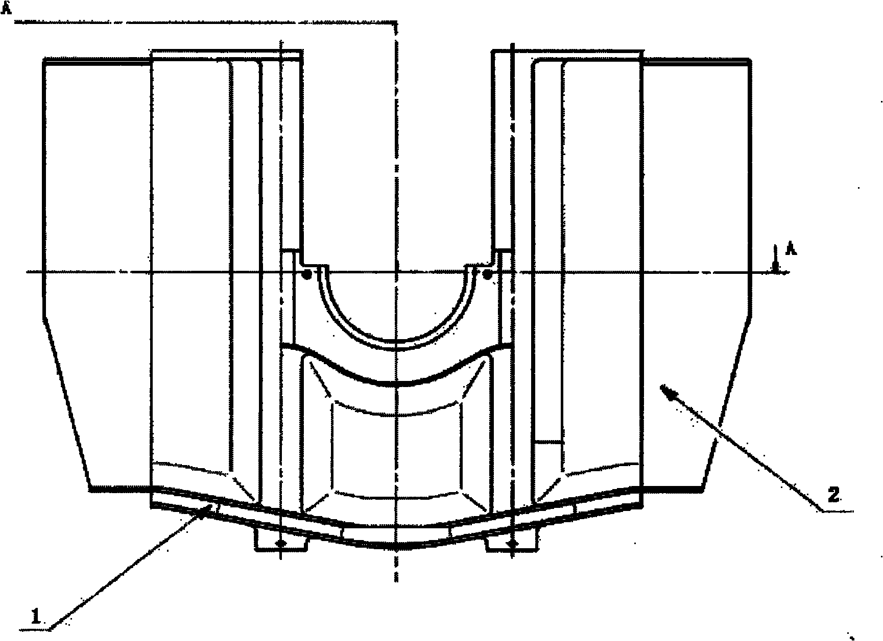
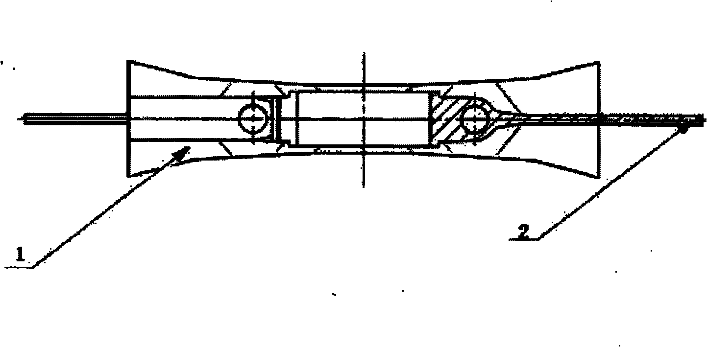
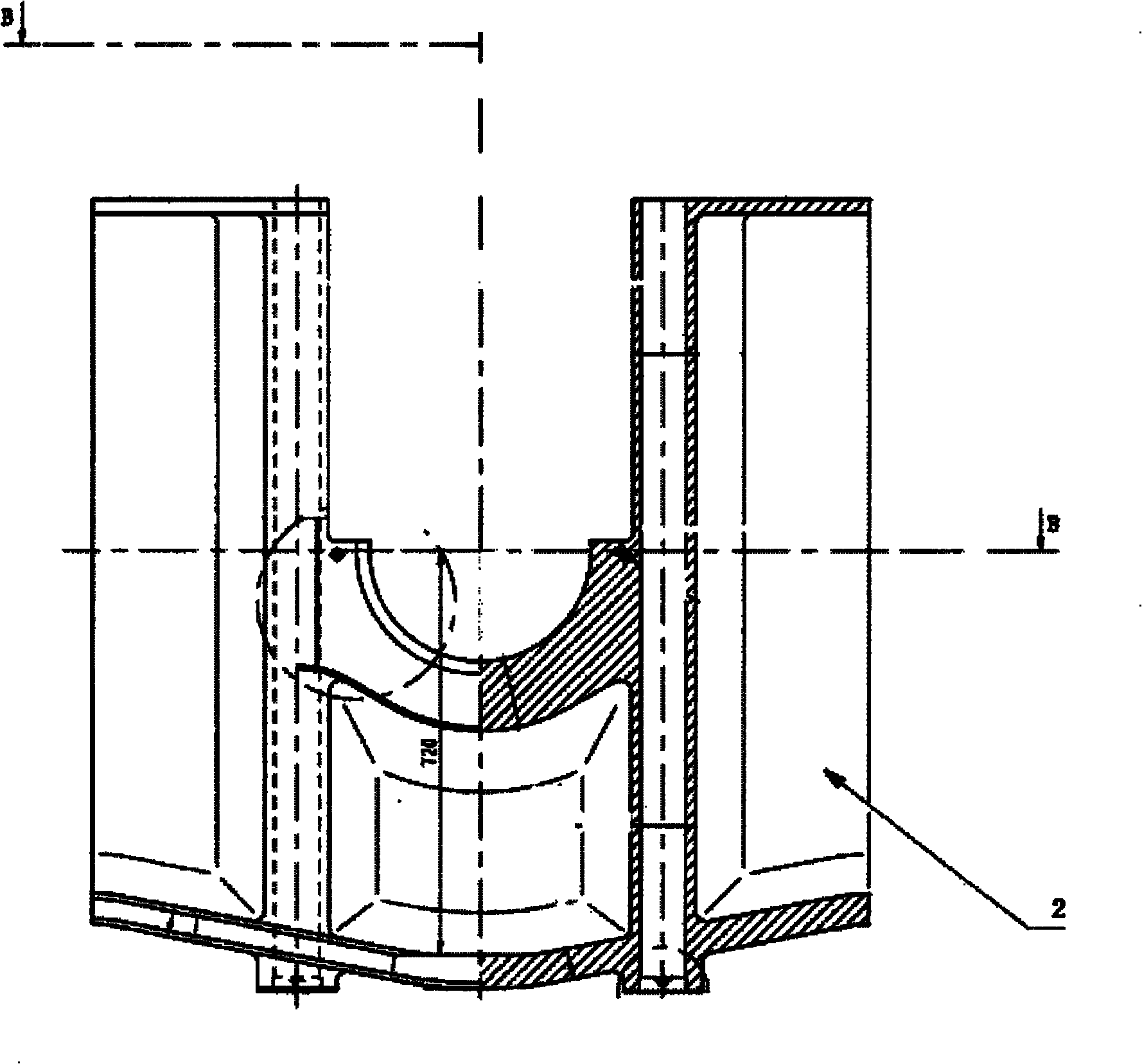
[0012] See Figure 3 to Figure 4 , a main bearing seat of a low-speed diesel engine, comprising a bearing seat 1 and wing plates 2 on both sides of the bearing seat, characterized in that a welding structure is adopted between the bearing seat 1 and the wing plates 2 on both sides of the bearing seat. Bearing seat 1 is made of casting, and wing plate 2 is made of steel plate, and double-sided grooves are opened on the steel plate during welding. The width of the wing plates on both sides of the bearing seat does not exceed the radial edge of the bearing seat. Since the width of the wing plate is greatly reduced, it can be 300mm in production. The overall width of the main bearing housing has also been significantly reduced.

[0013] Apparently, the above-mentioned embodiments of the present invention are only examples for clearly illustrating the present invention, rather than limiting the implementation of the present invention. For those of ordinary skill in the art, other c


PUM


Abstract

The invention discloses a main bearing block of a low-speed diesel engine, comprising a bearing block (1) and wing plates (2) on two sides of the bearing block, wherein a welding structure is welded between the bearing block (1) and the wing plates (2) on two sides of the bearing block. By adopting the structure, the invention can reduce the width of the thin wall part of a casting and fundamentally reduce the deformation and the appearance possibility of casting flaws; since the deformation can be well controlled by welding, the wing plates on two sides of the improved main bearing block are hardly deformed; in addition, the invention has simple structure, is easy to form and superior to an integrally-formed steel casting in the total production cost and the period.

Description


Claims


Application Information

Patent Timeline
Owner JIANGSU ANTAI POWER MACHINERY
Why Eureka
Try Eureka