Drum-gear angular flexible coupling

A technology of flexible couplings and gear couplings, which is applied in the direction of elastic couplings, couplings, bearing components, etc., can solve the problems of accelerated wear, high power transmission, and reduced service life of gear couplings. Achieve the effect of reducing the starting current power, increasing the service life of drum teeth, and transmitting large torque

Inactive Publication Date: 2011-08-24
李文聪
View PDF4 Cites 6 Cited by
  • Summary
  • Abstract
  • Description
  • Claims
  • Application Information

AI Technical Summary

Benefits of technology

This patented technology improves on drums used with automatic drive systems by adding an improved design feature called a diaphram group or overlayed diaphrageer group. These improvements allow the system to gradually shift from one type of motion to another without causing damage due to excessive bending stress caused by repeated use. Additionally, these designs increase the durability of the components involved while maintain their effectiveness at high speeds. Overall, they improve efficiency and reliance within the overall performance of the auto-drive system.

Problems solved by technology

This patented technical solution described in this patents solves issues related to traditional couplers used at different stages of their lifespan (the longer they last). However, these conventional solutions also cause significant vibrations or sound levels while operating heavy duty machines.

Method used


Image

  • Drum-gear angular flexible coupling
  • Drum-gear angular flexible coupling
  • Drum-gear angular flexible coupling

Examples


Embodiment Construction

[0024] The drum gear angular flexible coupling of the present invention will be further described in detail below in conjunction with the accompanying drawings.

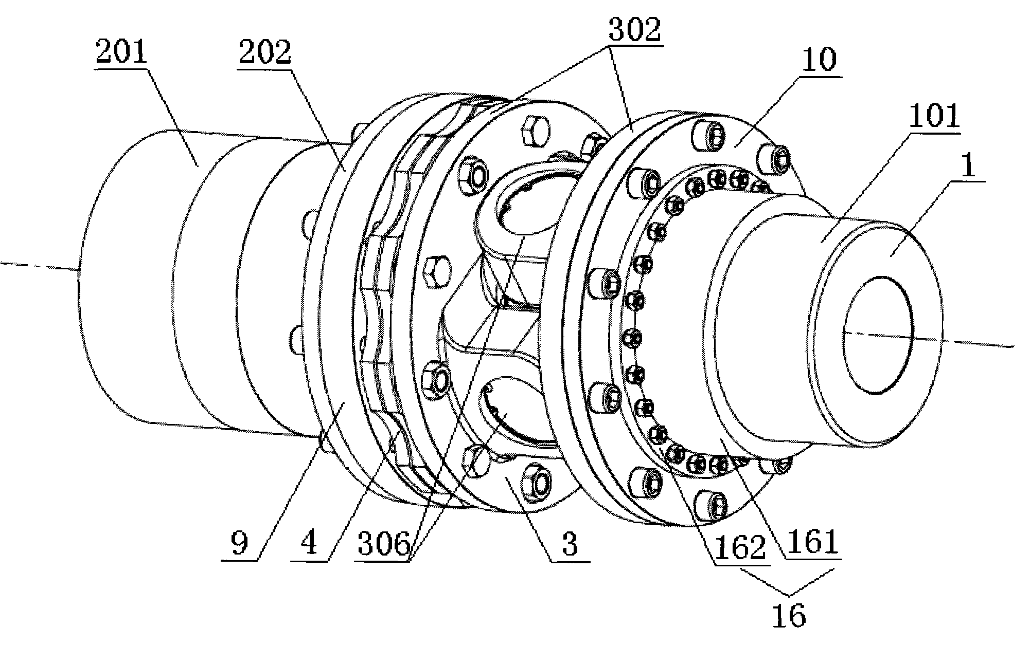
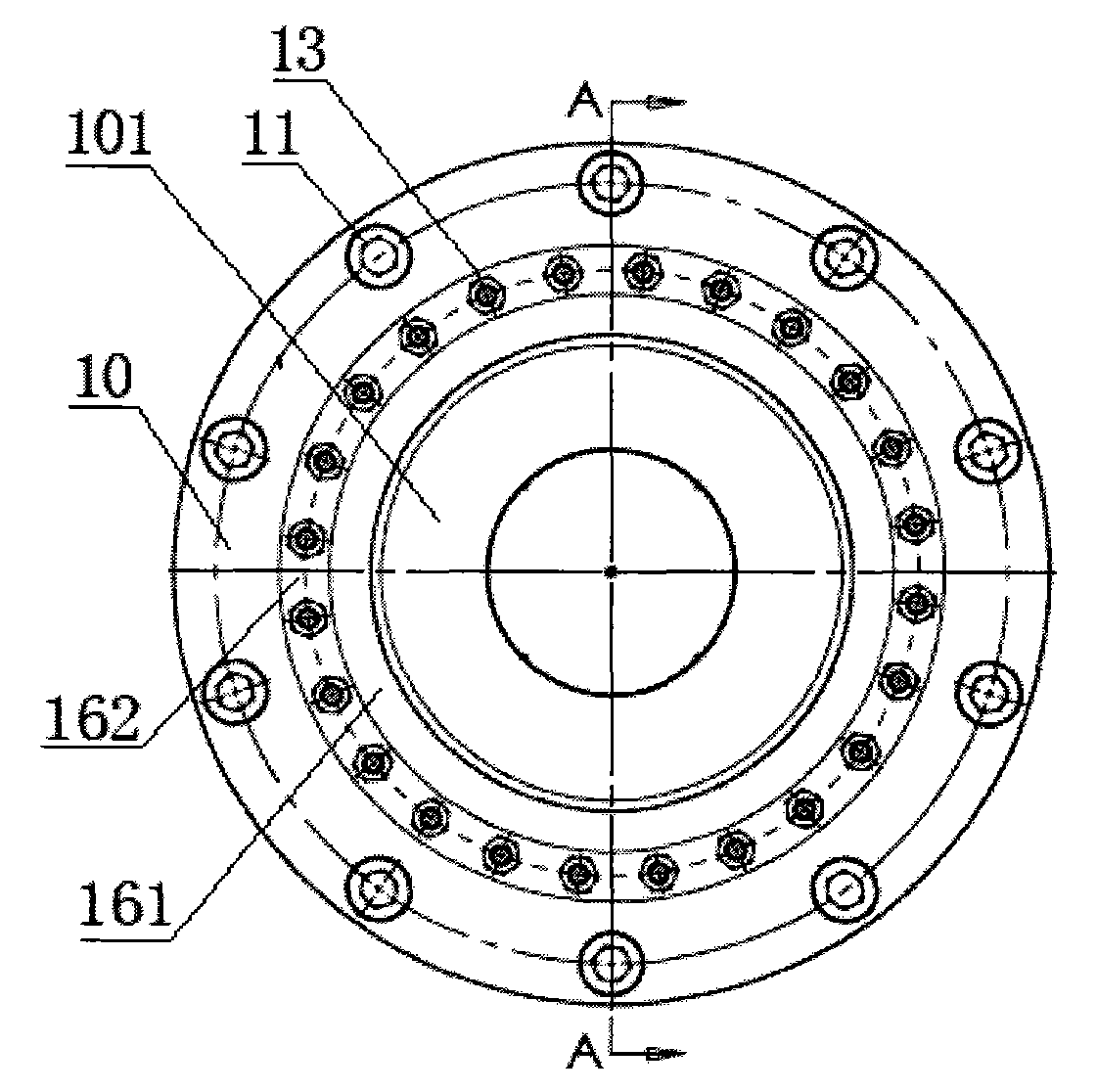
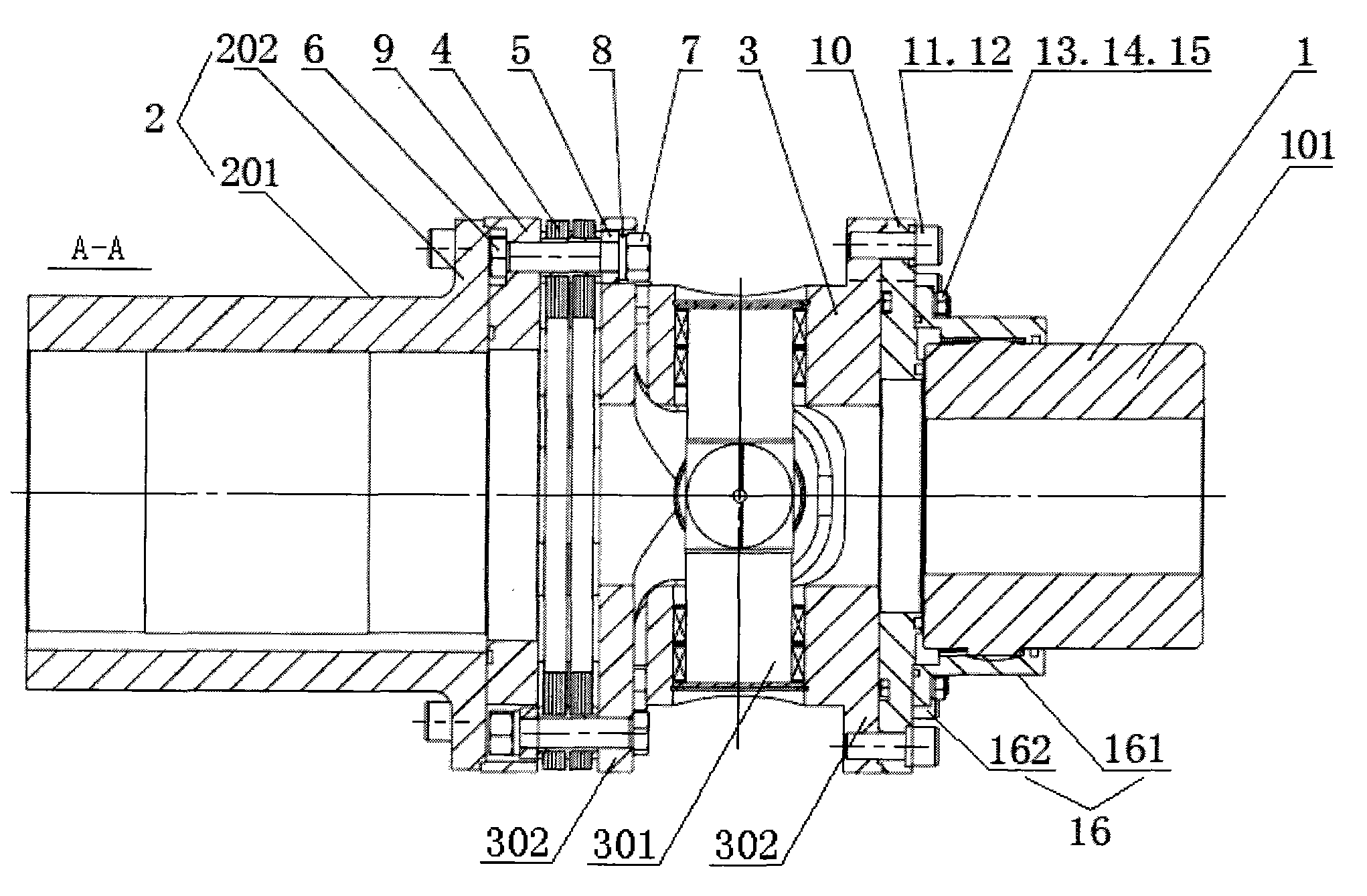
[0025] Such as Figure 1-4 As shown, the coupling of the present invention includes a driven machine end half coupling 1, a driving machine end half coupling 2, an angler 3, a diaphragm group 4, a drum gear coupling half coupling 16 and two a docking plate. The left side of the angler 3 is sequentially connected with the diaphragm group 4, the docking disc I9 and the half-coupling 2 of the main machine end from the inside to the outside, and the right side of the angler 3 is connected with the docking disc II10 and the drum tooth in sequence from the inside to the outside. Coupling half-coupling 16 and driven machine end half-coupling 1.

[0026] Such as Figure 4 As shown, the angler 3 includes a cross shaft 301 and two connection plates 302, the cross shaft 301 includes a grease nozzle 303 and four hollow shafts 30


PUM


Abstract

The invention belongs to the field of a transmission device and particularly relates to a drum-gear angular flexible coupling. The coupling provided by the invention comprises driving and driven terminal half-couplings, the half-coupling of the drum-gear coupling, an angular sensor, a diaphragm group and two butt disks, wherein the half-coupling of the drum-gear coupling is sheathed on the driven terminal half-coupling; the half-coupling of the drum-gear coupling and the driven terminal half-coupling are mutually meshed through internal and external gears; and one side of the angular sensor is sequentially connected with the diaphragm group, the butt disk I and the driving terminal half-coupling from interior to exterior, and the other side of the angular sensor is sequentially connected with the butt disk II, the half-coupling of the drum-gear coupling and the driven terminal half-coupling from interior to exterior. The coupling provided by the invention can automatically adjust, control and compensate the axial movement and angular offset of a driving machine and a driven machine, thereby enabling the wear degree of the gear surface to be reduced to the minimum; and the vibration caused by the transmission of the driving machine and the driven machine can be reduced, the noise can be lowered, and the service life of a drum gear can be prolonged, thereby achieving the functions of saving the energy and protecting the environment.

Description


Claims


Application Information

Patent Timeline
Owner 李文聪
Why Eureka
Try Eureka