Method for detecting leakage flow of automobile oil tank cover

A leakage flow and detection method technology, which is applied in the field of measuring force, torque and pressure devices, can solve the problems of complex operation process, high price and long detection time, and achieve high detection accuracy, good stability and high degree of automation Effect

Active Publication Date: 2011-09-14
SHANGHAI HUF AUTOMOTIVE LOCK CO LTD
View PDF5 Cites 11 Cited by
  • Summary
  • Abstract
  • Description
  • Claims
  • Application Information

AI Technical Summary

Benefits of technology

This technology allows for easy access by displaying different types of interfaces on computers or controlling devices that control valves used with gas tanks. It also includes advanced sensor technologies like pressure gauges, which help improve safety during handling operations while still providing accurate results. Additionally, it provides automatic monitoring capabilities when there's no human operator involved.

Problems solved by technology

This patented technical problem addressed in this patents relates to improving vehicle's ability to prevent accidental fires due to leaks or other issues with engine components while maintaining good performance for longer periods of use at lower cost compared to existing methods like fireproof caps.

Method used


Image

  • Method for detecting leakage flow of automobile oil tank cover
  • Method for detecting leakage flow of automobile oil tank cover
  • Method for detecting leakage flow of automobile oil tank cover

Examples


Embodiment 1

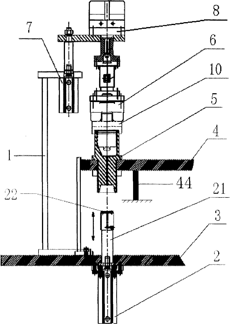
[0018] A method for detecting the leakage flow rate of the fuel tank cap of an automobile, which is carried out sequentially according to the following steps:

[0019] a. Prepare test instruments, b. Detect torque, c. Detect negative pressure flow, d. Detect leakage and e. Detect positive pressure flow, characterized by:

[0020] When preparing the test instrument in step a, proceed as follows: figure 1 and figure 2 As shown, the test instrument includes a bracket 1, a bottom plate telescopic cylinder 2, a piston 21, a sealing ring 22, a bottom plate 3, a rotating disc 4, an indexing rotator 41, a base 5, a tightening torque claw 6, a bracket telescopic cylinder 7 and a rotating Cylinder 8, bracket 1 is fixed on the base plate 3, the base plate telescopic cylinder 2 is vertically fixed below the base plate 3, a through hole is opened on the base plate 3, the piston 21 slides up and down along the inner wall of the base plate telescopic cylinder 2 and the top of the piston 21 pa


PUM


Abstract

The invention relates to the field of devices or methods for measuring force, torque and pressure, in particular to a method for detecting leakage flow of an automobile oil tank cover. The method for detecting leakage flow of an automobile oil tank cover comprises the following steps: a. preparing testing instruments; b. detecting torque; c. detecting negative flow; d. detecting leakage sum; and e. detecting positive flow. The method for detecting leakage flow of an automobile oil tank cover is characterized by carrying out Step a of preparing the testing instruments according to following steps, wherein the testing instrument comprises a bracket (1), a bottom plate telescopic air cylinder (2), a piston (21), a sealing ring (22), a bottom plate (3), a rotary round disk (4), a division rotator (41), a base (5), a tightening torque claw (6), a bracket telescopic air cylinder (7) and a rotary air cylinder (8). According to the method, the automatic degree is high, the stability is good, and the detection precision is high.

Description


Claims


Application Information

Patent Timeline
Owner SHANGHAI HUF AUTOMOTIVE LOCK CO LTD
Why Eureka
Try Eureka