Z-shaft independent controller for planar laser cutting machine

A plane laser and cutting machine technology, applied in laser welding equipment, manufacturing tools, welding equipment and other directions, can solve the problems affecting the use of plane laser cutting machine tools, the complex structure of the three-axis motion control card, and the poor reliability of the machine tool movement. Simple, highly reliable movement and smooth operation

Inactive Publication Date: 2011-10-05
江苏亚威创科源激光装备有限公司
View PDF6 Cites 1 Cited by
  • Summary
  • Abstract
  • Description
  • Claims
  • Application Information

AI Technical Summary

Benefits of technology

This technology allows for precise adjustment of the distance between two parts called cutter heads that are used during machining operations on materials such as metal or plastic products. It uses an optic sensor connected to a computer chip inside the device's housing to detect when there has been enough material remaining after being worked together. Based upon this detection data, software calculates how long each part needs to be moved before stopping its next step. By doing these calculations, the processor can determine which direction they should move at once based solely on their current location within space. Overall, this technology simplifies the process while improving efficiency and safety compared to traditional methods like servo systems.

Problems solved by technology

This patented technical problem addressed in this patents relates to improving the performance and efficiency of machining equipment that uses lightweight materials such as aluminum or plastic for various applications like aircraft construction. Current methods involve complicated structures involving multiple axis movements, resulting in lowered accuracy and reduced durability over time due to their complexity.

Method used


Image

  • Z-shaft independent controller for planar laser cutting machine
  • Z-shaft independent controller for planar laser cutting machine

Examples


Embodiment Construction

[0010] The present invention will be further described below in conjunction with specific drawings and embodiments.

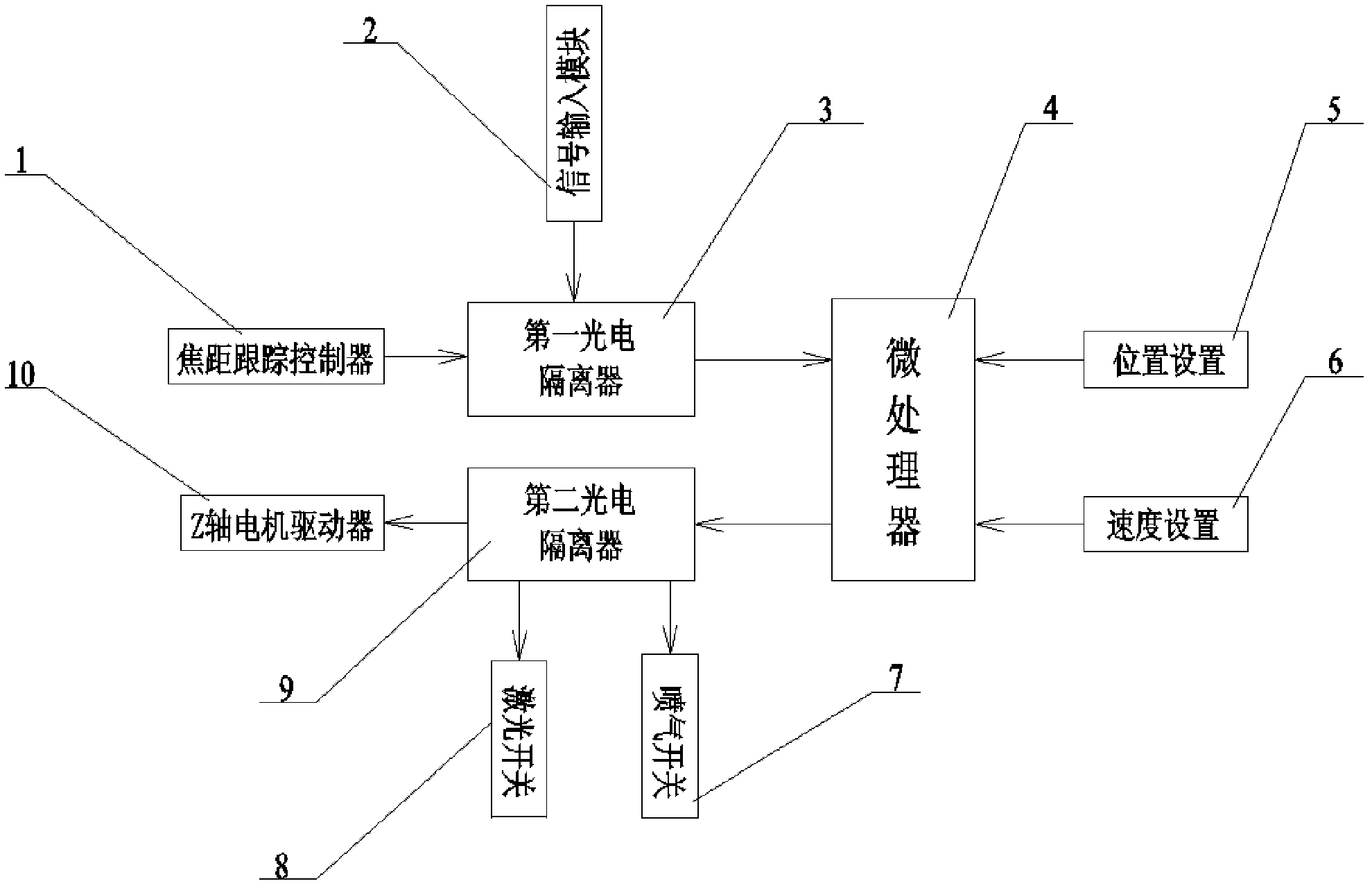
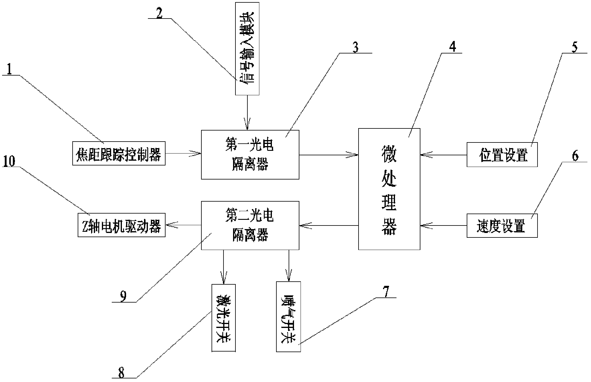
[0011] Such as figure 1 As shown: the present invention includes a focus tracking controller 1, a signal input module 2, a first photoelectric isolator 3, a microprocessor 4, a position setting module 5, a speed setting module 6, an air jet switch 7, a laser switch 8, a second photoelectric The isolator 9 and the Z-axis motor driver 10.

[0012] Such as figure 1 Shown: In order to reduce the complexity of the control controller of the plane laser cutting machine tool and improve the control accuracy, the Z-axis control mode of the machine tool is independent, and the Z-axis control no longer occupies the motion control resources of the machine tool. In order to be able to control the Z-axis, the Z-axis independent controller includes a microprocessor 4, which may be a single-chip microcomputer, ARM (Advanced RISC Machines) or other processing chips. The input e


PUM


Abstract

The invention relates to a Z-shaft independent controller for a planar laser cutting machine, which comprises a microprocessor, wherein an input end of the microprocessor is connected to a signal input module through a first photoelectric isolator; the input end of the microprocessor is also connected to a position setting module and a speed setting module; an output end of the microprocessor is connected to a second photoelectric isolator; the microprocessor of the Z-shaft independent controller receives a working state signal inputted by a cutting machine system through a signal receiving module; the microprocessor drives a Z-shaft motor driver to work at a corresponding state by utilizing the second photoelectric isolator according to the corresponding signal; the focusing track for a Z-shaft cutting head is realized by the microprocessor according to an input signal of a focusing tracking controller; and the position setting module and the speed setting module are used for setting the running position and speed of the Z-shaft motor driver. The running precision is high. After being independently controlled, the control system of the cutting machine has the advantages of simple structure, low use cost, high running reliability, running stability, safety and reliability.

Description


Claims


Application Information

Patent Timeline
Owner 江苏亚威创科源激光装备有限公司
Why Eureka
Try Eureka