Transformer oil tank

A technology for a transformer oil tank and a box body is applied in the field of transformer oil tanks, which can solve the problems of difficult assembly and transportation, unsightly appearance, and difficult maintenance, and achieve the effects of simple and lightweight structure, good heat dissipation performance and high mechanical strength.

Inactive Publication Date: 2012-02-22
SUZHOU DINGNENG ELECTRIC POWER EQUIP
View PDF9 Cites 2 Cited by
  • Summary
  • Abstract
  • Description
  • Claims
  • Application Information

AI Technical Summary

Problems solved by technology

[0003] The traditional transformer oil tank is made by welding a large number of reinforcing iron and reinforcing plates to improve its mechanical strength. The manufacturing requirements of its structure are relatively low, but the disadvantages are also obvious. Weld seams and welding slag are not conducive to the adhesion of surface paint, and the structure is complex and unsightly. For example, leakage under the reinforced iron is not easy to detect, and maintenance is also difficult. With the continuous increase of fuel tank specifications, its design, manufacture and maintenance are becoming more and more difficult. The larger the size, the poorer the heat dissipation effect, and the need to install an auxiliary heat dissipation device, the further increase the complexity of the structure, the weight and size of the fuel tank cannot be well controlled, and the assembly and transportation are not easy

Method used


Image

  • Transformer oil tank
  • Transformer oil tank
  • Transformer oil tank

Examples


Example Embodiment

[0011] The present invention will be further explained below in conjunction with the drawings.

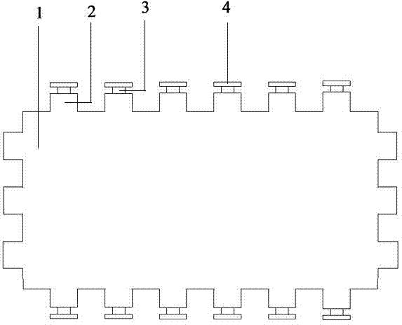
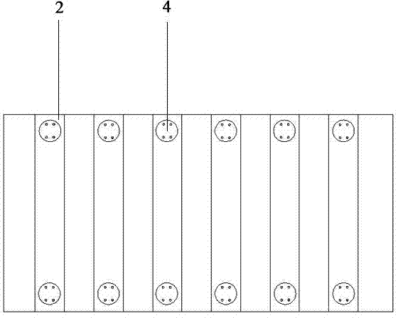
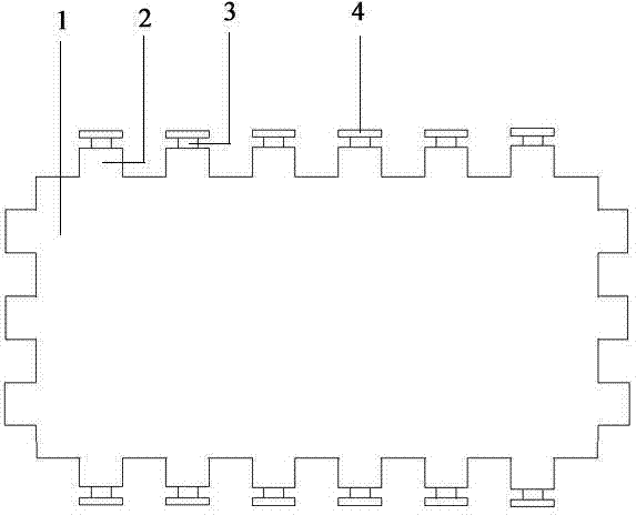
[0012] Such as figure 1 , 2 As shown, the tank body 1 is a bell-jar type, and a plurality of convex corrugations 2 parallel to each other are arranged on the wall of the tank. The wall of the tank is formed by one-step corrugation, and the upper and lower ends of the corrugations 2 on the two opposite long end faces Each nozzle 3 is provided with a flange 4 outside each nozzle 3, the flange 4 has a slotted structure and a limiting structure, and the connection between the nozzle 3 and the flange 4 is provided with a nitrile rubber gasket ( Not shown in the figure).

[0013] The wall of the corrugated forming box is made of a large folding machine, which eliminates the use of reinforcing iron, reinforcing ribs or reinforcing plates. The structure is simple and light, reduces welding seams, saves welding man-hours, and is more conducive to paint coating. It is also easier to repair leaks. T


PUM


Abstract

The invention discloses a transformer oil tank. The transformer oil tank comprises a tank box and is characterized in that: the tank body has a bell-jar structure; a plurality of raised corrugations which are parallel to one another are arranged on each tank wall of the tank body; the tank walls are formed through corrugation molding at one time; pipe mouths are formed in the corrugations; and flanges are arranged on the external parts of the pipe mouths. The transformer oil tank is simple in structure, light and handy, attractive in appearance, high in mechanical strength and radiating performance, and good in noise reduction effect, and is convenient to manufacture and maintain.

Description


Claims


Application Information

Patent Timeline
Owner SUZHOU DINGNENG ELECTRIC POWER EQUIP
Why Eureka
Try Eureka