Leak-proof protection system

A protection system and anti-leakage technology, applied in the direction of polycrystalline material growth, crystal growth, single crystal growth, etc., can solve the problem of poor sealing of polycrystalline ingot furnace body, and achieve the effect of ensuring production quality

Inactive Publication Date: 2012-07-11
ZHEJIANG HONGYE NEW ENERGY
View PDF19 Cites 0 Cited by
  • Summary
  • Abstract
  • Description
  • Claims
  • Application Information

AI Technical Summary

Benefits of technology

This invention provides an improved method for prevention of leaks during crystal growth by utilizing both negative (vacuums) or positive (pressure), which helps improve the efficiency of producing high purity silicon wafers with good properties.

Problems solved by technology

In this patented technical problem addressed by the inventor's researchers are finding better ways to improve the seals on small crucibles during manufacturing processes that use molten materials like monoclonal or polycleated silicone (MCS).

Method used


Image

  • Leak-proof protection system
  • Leak-proof protection system

Examples


Embodiment Construction

[0008] The technical solution of the present invention will be described in detail below with reference to the accompanying drawings.

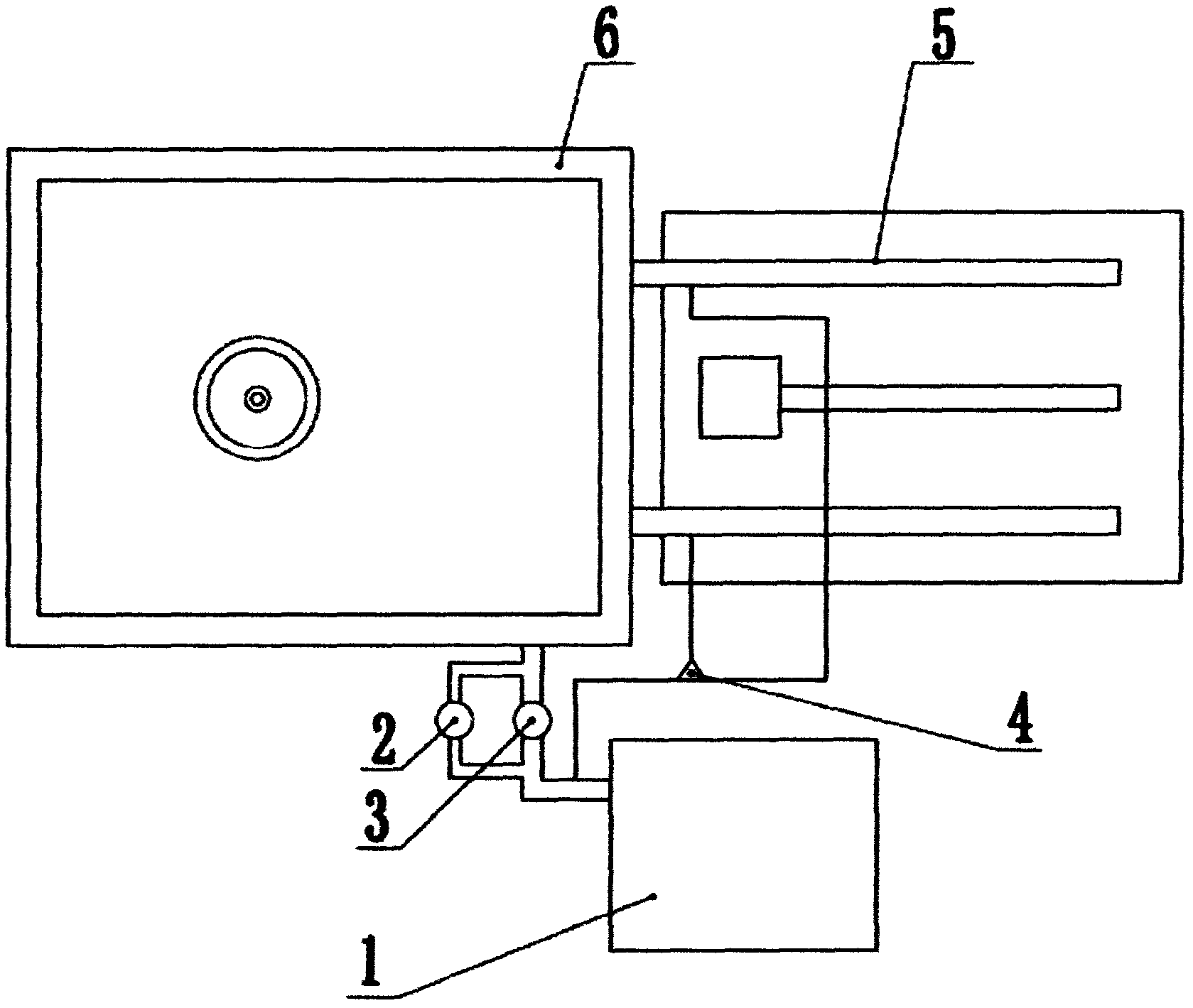
[0009] Such as figure 1 As shown, the anti-leakage protection system includes a vacuum pump 1. The vacuum pump 1 is connected to a polycrystalline furnace 6 through a bypass valve 2 and a pump main valve 3 respectively. One end of the pipeline branch 4 is connected to the vacuum pump 1, and the other end of the pipeline branch 4 They are connected to two sliding screws 5 respectively. The polycrystalline furnace 6 is also equipped with an insulating door panel, and a sealing ring is arranged between the insulating door panel and the sliding screw 5 to prevent air from entering the furnace body from between the insulating door panel and the sliding screw 5.

[0010] During the operation of the polycrystalline furnace 6, the vacuum pump 1 is in a normally open state, and the excess gas in the polycrystalline furnace 6 is pumped away through the pump ma


PUM


Abstract

The invention provides a leak-proof protection system which comprises a vacuum pump; the vacuum pump is connected with a polycrystalline furnace respectively through a bypass valve and a pump main valve; one end of a branch of a pipeline is connected with the vacuum pump, and the other end of the branch of the pipeline is respectively connected with two sliding screw rods, so that a leak-proof function can be reached; the polycrystalline furnace is also provided with a heat insulation door plate in a matching way; and a sealing ring is arranged between the heat insulation door plate and the sliding screw rods, so that the air is prevented form entering into a furnace body through the part between the heat insulation door plate and the sliding screw rods. According to the leak-proof protection system, the leakproofness of the polycrystalline furnace can be guaranteed in a way of double insurance through two vacuumizing channels, so that the production quality of the polycrystalline furnace can be better guaranteed.

Description


Claims


Application Information

Patent Timeline
Owner ZHEJIANG HONGYE NEW ENERGY
Why Eureka
Try Eureka