Petroleum fluorescence collecting and analyzing method based on charge coupled element optical fiber system

A technology of charge-coupled element and optical fiber system, applied in fluorescence/phosphorescence, material excitation analysis, etc., can solve the problems of bulky, cumbersome, unsuitable for oilfield use requirements, etc., and achieve the effect of small size, convenient operation and light weight

Inactive Publication Date: 2012-12-19
天津陆海石油设备系统工程有限责任公司
View PDF7 Cites 4 Cited by
  • Summary
  • Abstract
  • Description
  • Claims
  • Application Information

AI Technical Summary

Problems solved by technology

At present, the fluorescence analysis methods used by oilfield logging companies are all based on the fluorescence analysis system of photomultip

Method used


Image

  • Petroleum fluorescence collecting and analyzing method based on charge coupled element optical fiber system
  • Petroleum fluorescence collecting and analyzing method based on charge coupled element optical fiber system

Examples


Embodiment Construction

[0015] The present invention will be further described below in conjunction with accompanying drawing.

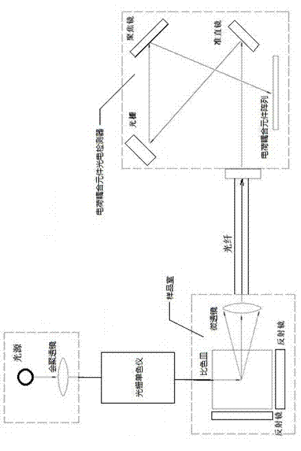
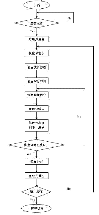
[0016] refer to figure 1 and figure 2 , the method includes the following steps:

[0017] (1). Start the charge-coupled device photodetector to collect the optical background dark noise of the charge-coupled device fiber optic system;

[0018] (2). Put the cuvette containing the petroleum fluorescent sample into the sample chamber;

[0019] (3). Turn on the light source and the grating monochromator, and reset the grating monochromator to the initial wavelength, which can be set by the user;

[0020] (4). Set the scanning stop wavelength and scanning step of the grating monochromator;

[0021] (5). Set the acquisition integration time of the charge-coupled device photodetector;

[0022] (6). Use the control program to control the charge-coupled element photodetector to integrate and record the sample fluorescence under the excitation light of the initial wavelength; then


PUM


Abstract

The invention relates to a petroleum fluorescence collecting and analyzing method based on a charge coupled element optical fiber system. According to the method, a charge coupled element photoelectric detector is utilized to carry out fluorescence detection; a charge coupled element array in the charge coupled element photoelectric detector can be used for collecting wavelength-light strength corresponding data only by carrying out photon integration without grating rotation beam split, so that the entire analysis period is shortened; the analysis period is 155 seconds; and the production efficiency of an oil field is improved; the entire analysis system is small in size, light in weight, convenient for operation and strong in impact resistance, and is suitable for severe analysis environment without a lab-level severe analysis environment condition; an optical fiber is used as a transmission channel of a light path system, so that the traditional lens type symmetrical light path can be replaced; and the size and the weight of the entire analysis system can be reduced while the environmental suitability of the system is improved, so that the integrally-formed optical system is more suitable for the more narrower using condition of the oil field in situ and a condition that an instrument generally needs to be transported.

Description


Claims


Application Information

Patent Timeline
Owner 天津陆海石油设备系统工程有限责任公司
Why Eureka
Try Eureka