Bolting component for corrugated steel plate and plain steel plate and manufacturing process
A corrugated steel plate and manufacturing process technology, applied in the direction of connecting members, thin plate connections, building structures, etc., can solve problems such as inability to fasten connection, and achieve the effects of stable connection, simple and convenient operation, and high rigidity
- Summary
- Abstract
- Description
- Claims
- Application Information
AI Technical Summary
Benefits of technology
Problems solved by technology
Method used
Image

Examples
Embodiment 1
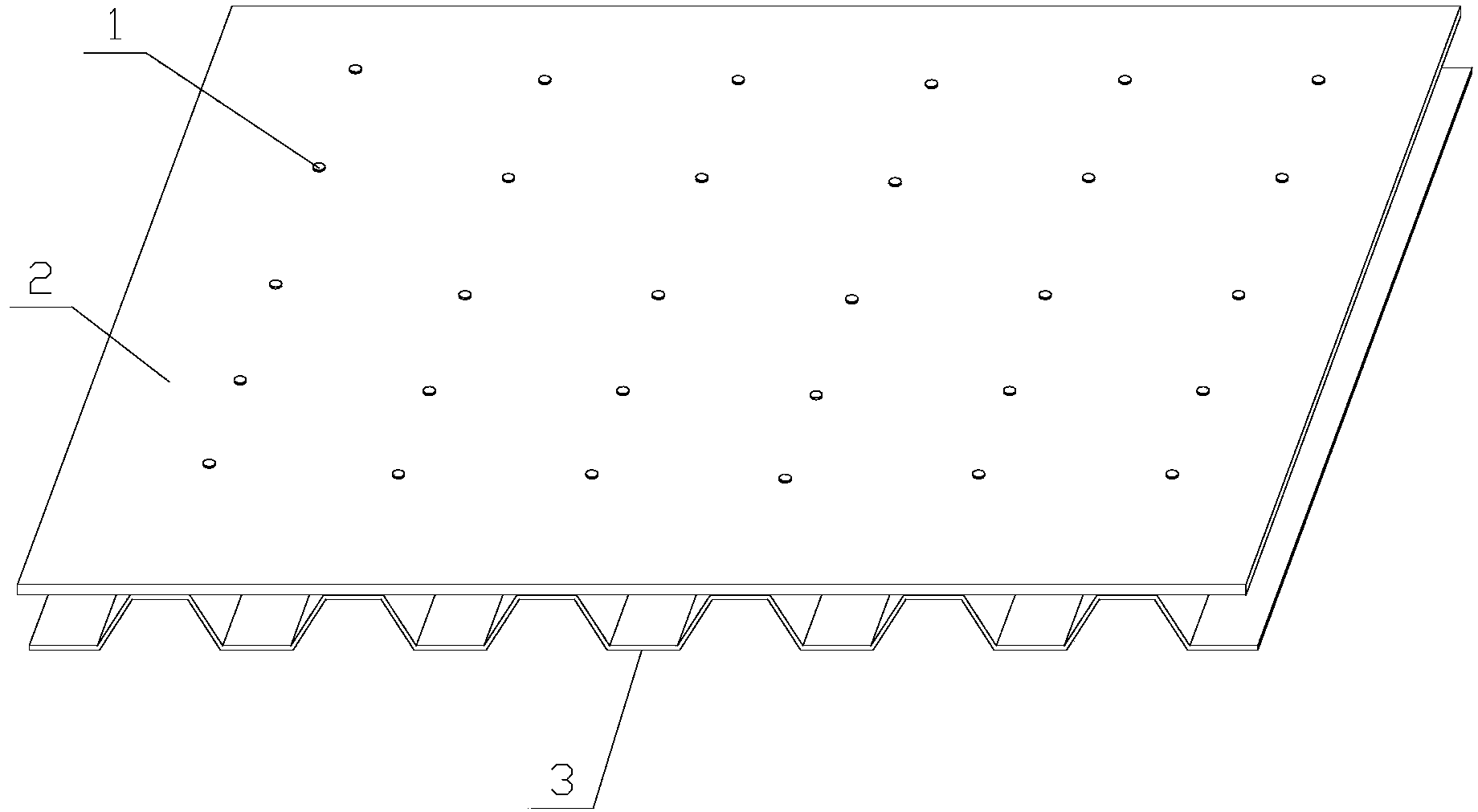
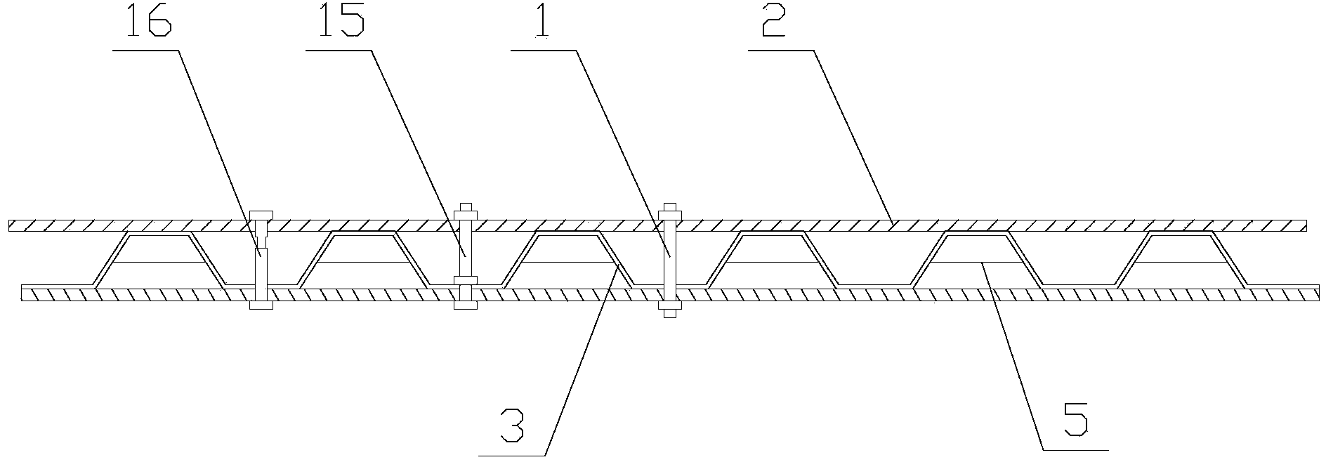
[0034] Corrugated steel plate and flat steel plate bolted components, such as figure 1 As shown, it includes a corrugated steel plate 3 and a flat steel plate 2. The corrugated steel plate 3 and the flat steel plate 2 have connecting holes, and the connecting screw 1 passes through the connecting holes on the corrugated steel plate 3 and the flat steel plate 2, and the corrugated steel plate 3, The flat steel plates 2 are joined together.
[0035] The crest position of the corrugated steel plate 3 covers the flattened steel plate 2 .
[0036] The connecting screw rod 1 is a long anti-skid bolt 15 .
[0037] The cross section of the corrugated steel plate 3 is trapezoidal wave. The corrugated steel plate 3 adopts a trapezoidal corrugated steel plate, so its contact surface with the flat steel plate 2 is a plane, which is convenient for the cooperation and installation of the overall structure.
[0038] The manufacturing process of bolted components between corrugated steel plat
Embodiment 2
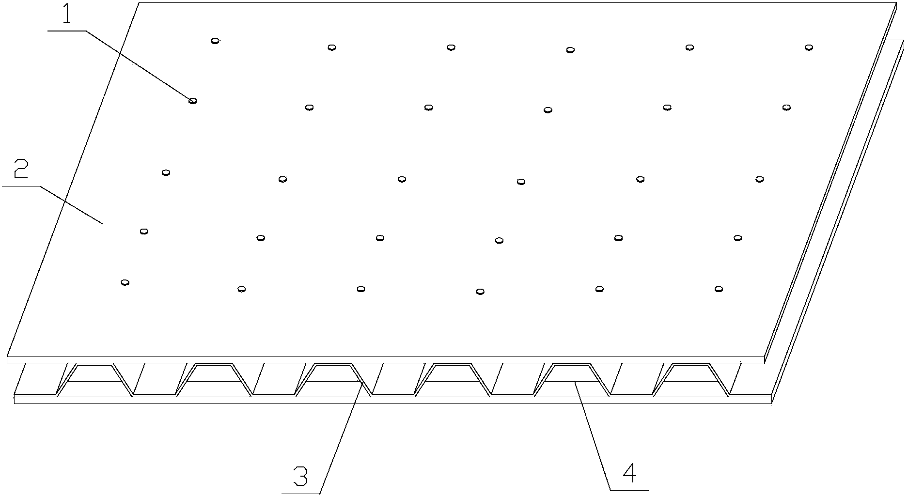
[0043] Corrugated steel plate and flat steel plate bolted components, such as figure 2 , 3 As shown, it includes a corrugated steel plate 3 and a flat steel plate 2. The corrugated steel plate 3 and the flat steel plate 2 have connecting holes, and the connecting screw 1 passes through the connecting holes on the corrugated steel plate 3 and the flat steel plate 2, and the corrugated steel plate 3, The flat steel plates 2 are joined together.
[0044] The corrugated steel plate 3 is one piece, and the flat steel plate 2 is two pieces. The corrugated steel plate 3 is located between the two flat steel plates 2. There are connecting holes on the corrugated steel plate 3 and the two flat steel plates 2. The connecting hole on the flat steel plate 2 connects the corrugated steel plate 3 and two flat steel plates 2.
[0045] The crest position of the corrugated steel plate 3 covers the flattened steel plate 2 . The flat steel plate 2 is arranged on the upper and lower sides of the
Embodiment 3
[0055] Corrugated steel plate and flat steel plate bolted components, such as Figure 4 As shown, it includes a corrugated steel plate 3 and a flat steel plate 2. The corrugated steel plate 3 and the flat steel plate 2 have connecting holes, and the connecting screw 1 passes through the connecting holes on the corrugated steel plate 3 and the flat steel plate 2, and the corrugated steel plate 3, The flat steel plates 2 are joined together.
[0056] There are more than two corrugated steel plates 3, and more than three flat steel plates 2. The corrugated steel plates 3 are located between two flat steel plates 2. There are connecting holes on the corrugated steel plates 3 and the flat steel plates 2. The connecting screw 1 passes through the corrugated steel plates 3 and The connecting holes on two adjacent flat steel plates 2 connect the corrugated steel plates 3 and the two adjacent flat steel plates 2 .
[0057] The crest position of the corrugated steel plate 3 covers the fla
PUM
 Abstract
Description
Claims
Application Information
 - R&D Engineer
- R&D Manager
- IP Professional
- Industry Leading Data Capabilities
- Powerful AI technology
- Patent DNA Extraction
Browse by: Latest US Patents, China's latest patents, Technical Efficacy Thesaurus, Application Domain, Technology Topic.
© 2024 PatSnap. All rights reserved.Legal|Privacy policy|Modern Slavery Act Transparency Statement|Sitemap