Supporting steel pipe device of underground added layer of existing building and installing method of supporting steel pipe device

A technology for adding layers underground and supporting steel pipes, which is applied in construction, building maintenance, building construction, etc. It can solve problems such as difficult parking, undesigned underground parking lot, lack of foresight, etc., and achieve light lifting equipment and less insertion of steel pipes The effect of reducing the time and reducing the engineering cost

Active Publication Date: 2013-12-11
山东水发市政建设有限公司
View PDF6 Cites 2 Cited by
  • Summary
  • Abstract
  • Description
  • Claims
  • Application Information

AI Technical Summary

Benefits of technology

This patented technology allows for faster connections between two different types of metal tubulars used by older structures without requiring expensive machinery. It also improves safety during installation while minimizing damage caused from heavy loads on workers' legs when installing new structural components. Additionally, it simplifies the process of reusing old materials with minimal labor costs. Overall, this innovation makes connecting these metals more efficient than traditional methods like welded bolts.

Problems solved by technology

This patented describes a problem where older buildings without underground spaces cannot efficiently develop their own underground facilities for better environmental protection purposes. Current methods involve developing underground structures that require significant effort from architectural designers who often only work at specific locations within limited areas. There is also concern over potential safety hazards caused during construction processes when workers enter these sites while carrying out various tasks like digging trenches through which they may fall down.

Method used


Image

  • Supporting steel pipe device of underground added layer of existing building and installing method of supporting steel pipe device
  • Supporting steel pipe device of underground added layer of existing building and installing method of supporting steel pipe device
  • Supporting steel pipe device of underground added layer of existing building and installing method of supporting steel pipe device

Examples


Embodiment 1

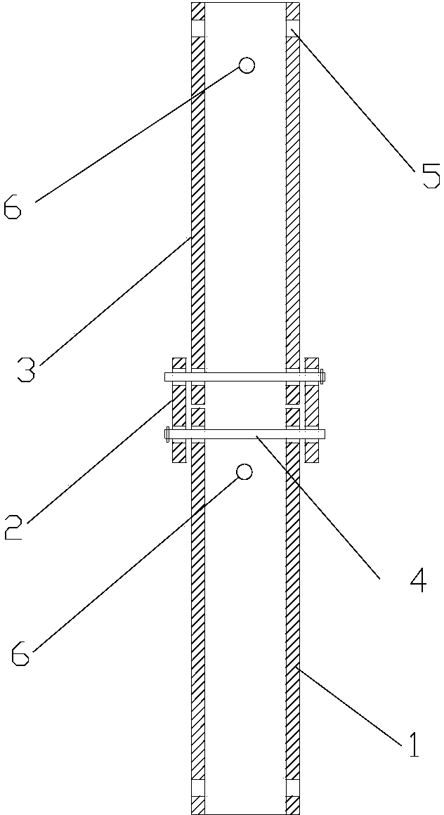
[0032] figure 1 , Figure 3-Figure 7 As shown, the existing supporting steel pipe device for building underground storeys includes at least two sections of steel pipes, and the two adjacent sections of steel pipes (ie, the upper section of steel pipe 3 and the lower section of steel pipe 1 ) are connected by jacket type steel pipe joints 2 and short pins 4 , the inner diameter of the jacket-type steel pipe joint 2 is greater than the outer diameters of two adjacent sections of steel pipes. The upper end of the steel pipe is provided with a first jack 6 that can be inserted into a long bolt outside the length range of the jacket-type steel pipe joint 2; The second insertion hole 5 of the short plug is inserted, and the first plug 6 and the second plug 5 are staggered by 90° on the circular section of the same steel pipe.

[0033] A method for installing a supporting steel pipe device for adding floors underground in an existing building, comprising:

[0034] (1) Drill holes on

Embodiment 2

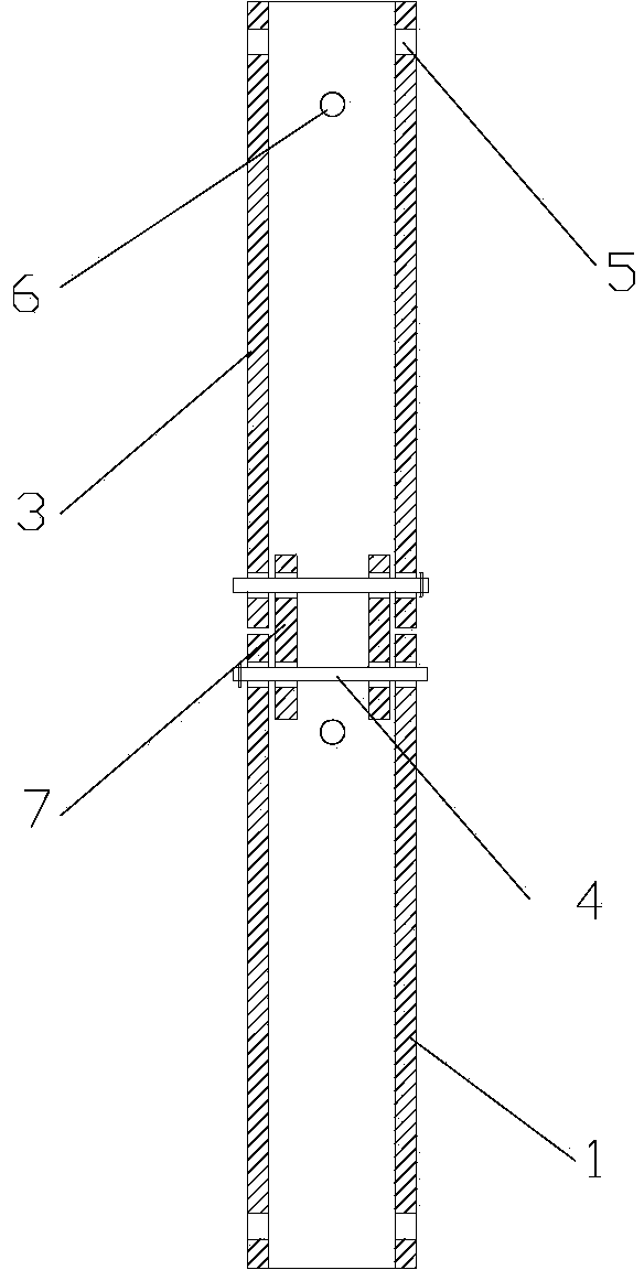
[0044] Such as Figure 2-Figure 5 As shown, the supporting steel pipe device for building underground storeys in existing buildings includes at least two sections of steel pipes, and the two adjacent sections of steel pipes (that is, the upper section of steel pipe 3 and the lower section of steel pipe 1 ) are connected by interpolated steel pipe joints 2 and short pins 4 connection, the outer diameter of the plug-in steel pipe joint 7 is smaller than the inner diameters of two adjacent sections of steel pipes. The upper end of the steel pipe and outside the length range of the interpolated steel pipe joint 7 are provided with a first socket 6 that can be inserted into a long bolt; The second insertion hole 5 of the short plug is inserted, and the first plug 6 and the second plug 5 are staggered by 90° on the circular section of the same steel pipe.

[0045] A method for installing a supporting steel pipe device for adding floors underground in an existing building, comprising:


PUM


Abstract

The invention discloses a supporting steel pipe device of an underground added layer of an existing building. The supporting steel pipe device comprises at least two steel pipes, every two adjacent steel pipes are connected with each other through a steel pipe joint and short pins, and a first plughole in which a long pin can be plugged is formed in the position, outside the range of the length of each steel pipe joint, at the upper end of each steel pipe; each steel pipe joint and every two adjacent steel pipes are provided with corresponding second plugholes in which the short pins can be plugged, and the first plughole and the second plugholes in each steel pipe are arranged by being staggered by 90 degrees. Meanwhile, the invention further discloses an installing method of the supporting steel pipe device. The supporting steel pipe device guarantees that the steel pipes bear force reasonably after being connected, achieves rapid and convenient connection of the steel pipes, shortens the time for inserting the steel pipes into boreholes, and lowers the risk of borehole collapse. Meanwhile, horizontal tied rod members can be installed conveniently, and stability of the steel pipes is guaranteed. The steel pipes can be recycled, so that engineering cost is lowered. Required hoisting equipment is portable, construction is applicable to basements and other narrow and small space, and technical support is provided for the underground added layer of the existing building.

Description


Claims


Application Information

Patent Timeline
Owner 山东水发市政建设有限公司
Why Eureka
Try Eureka