Position sensor assembly for manual transmission and manual transmission

A technology for manual transmissions and sensor components, applied to components with teeth, transmission control, belts/chains/gears, etc., can solve problems such as high development costs, oil leakage at switches, and low contact life, and achieve improved Stability and insulation performance, easy installation and disassembly, and the effect of improving accuracy

Inactive Publication Date: 2014-03-05
GREAT WALL MOTOR CO LTD
View PDF10 Cites 6 Cited by
  • Summary
  • Abstract
  • Description
  • Claims
  • Application Information

AI Technical Summary

Problems solved by technology

Neutral position sensors are generally perforated, switch-type, etc. The signal output of this structure is not very accurate and there is a risk of oil leakage at the switch. The magnet is generally external, and the development cost is high.
[0003] The reversing light switch is generally a mechanical contact type, which has the following disadvantages:

Method used


Image

  • Position sensor assembly for manual transmission and manual transmission
  • Position sensor assembly for manual transmission and manual transmission

Examples


Embodiment Construction

[0026] Embodiments of the present invention are described in detail below, examples of which are shown in the drawings, wherein the same or similar reference numerals designate the same or similar elements or elements having the same or similar functions throughout. The embodiments described below by referring to the figures are exemplary and are intended to explain the present invention and should not be construed as limiting the present invention.

[0027] In describing the present invention, it should be understood that the terms "center", "longitudinal", "transverse", "length", "width", "thickness", "upper", "lower", "front", " Orientation or position indicated by "back", "left", "right", "vertical", "horizontal", "top", "bottom", "inner", "outer", "clockwise", "counterclockwise", etc. The relationship is based on the orientation or positional relationship shown in the drawings, and is only for the convenience of describing the present invention and simplifying the descriptio


PUM


Abstract

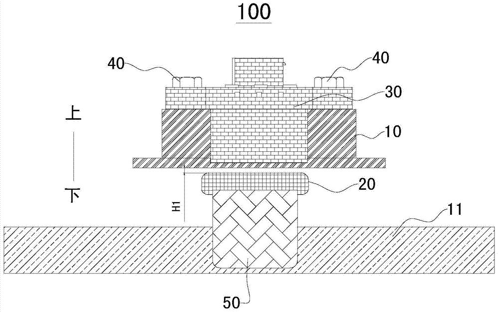
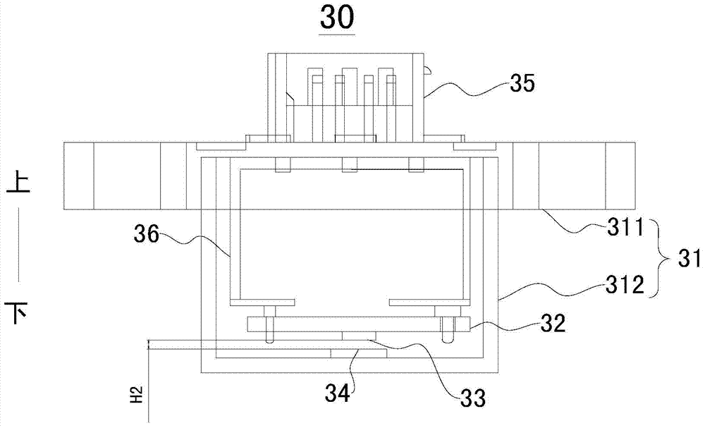
The invention provides a position sensor assembly for a manual transmission and the manual transmission. The manual transmission comprises a transmission shell and a gear shift shaft located in the transmission shell. The position sensor assembly comprises a magnetism converging body which is suitable for being arranged on the gear shifting shaft, a sensor which is suitable for being fixed on the outer surface of the transmission shell and is separated from the magnetism converging body by the transmission shell. The sensor is opposite to the magnetism converging body and comprises a shell, a circuit board, a Hall chip, a magnet and a connector clip, wherein the magnet is fixed in the shell. According to the position sensor assembly for the manual transmission, the sensor is arranged on the outer surface of the transmission shell, and therefore due to the fact that the installation manner of the sensor is a non-through manner, the risks of oil leakage of the transmission shell will not exist at the sensor.

Description


Claims


Application Information

Patent Timeline
Owner GREAT WALL MOTOR CO LTD
Why Eureka
Try Eureka