Floor pan for connecting a roof-mounted cooling device to the roof of a switch cabinet

A cooling device, switchgear technology, applied in the direction of modification using gaseous coolant, cooling/ventilation of substations/switchgear, construction parts of electrical equipment, etc.

Active Publication Date: 2014-04-23
RITTALWERK RUDOLF LOH GMBH & CO KG
View PDF5 Cites 1 Cited by
  • Summary
  • Abstract
  • Description
  • Claims
  • Application Information

AI Technical Summary

Problems solved by technology

[0003] However, it can happen that the thermal conditions in the interior of the switchgear are cha

Method used


Image

  • Floor pan for connecting a roof-mounted cooling device to the roof of a switch cabinet
  • Floor pan for connecting a roof-mounted cooling device to the roof of a switch cabinet
  • Floor pan for connecting a roof-mounted cooling device to the roof of a switch cabinet

Examples


Embodiment Construction

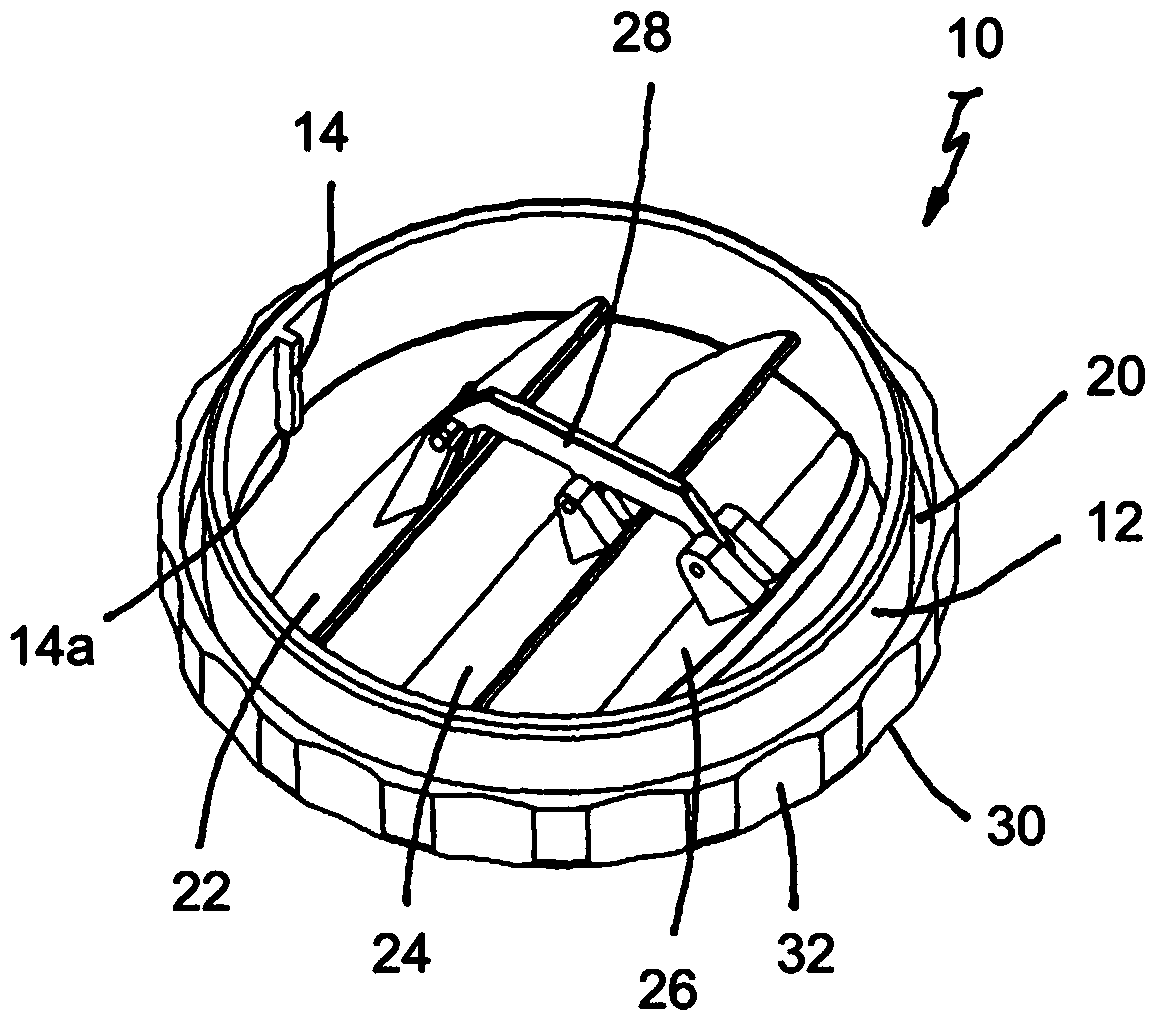
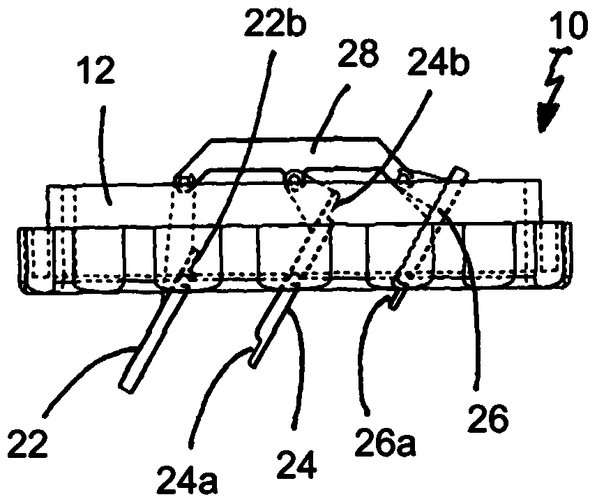
[0019] According to a preferred embodiment of the present invention, it is used to connect the cooling device arranged on the top of the cabinet to the top of the switch cabinet, so as to connect the inner space of the switch cabinet with the internal circulation of the coolant circuit of the cooling device arranged on the top of the cabinet. A coupled bottom trough provided with a pipe head 10 for an air outlet, as in Figure 1 to Figure 3 shown in different diagrams. This pipe head 10 fits over the existing pipe socket and can thus be replaced or retrofitted relatively easily.

[0020] figure 1 It shows a perspective view of the pipe head 10 in a basically installed state viewed from the side of the cooling device arranged on the top of the cabinet. In the hollow cylindrical body 12, the outer diameter of which corresponds substantially to the inner diameter of the sleeve to be fitted with the head 10, three ventilation vanes 22, 24, 26 are provided which are hinged on a leve


PUM


Abstract

The invention relates to a floor pan (100) for connecting a roof-mounted cooling device to the roof of a switch cabinet for coupling an inner chamber of the switch cabinet to the inner circuit of the refrigerant circulation of the roof-mounted cooling device, having at least one air inlet opening (106) aligned with the hot air outlet of the inner chamber of the switch cabinet and at least one air outlet opening communicating with the cold air inlet(s) of the inner chamber of the switch cabinet, wherein the air inlet opening(s) and the air outlet opening(s) are provided in the base (102) of the floor pan (100) and are covered by ventilation grilles (108) or ventilation louvres (22, 24, 26). The floor pan is characterized in that a plurality of air outlet openings are arranged surrounding the at least one air inlet opening (106) and at last some of the air outlet openings are covered by ventilation louvres (22, 24, 26) that are pivotable about an axis running in the plane of the floor (102) and are rotatable about an axis running perpendicular to the plane of the floor (102).

Description


Claims


Application Information

Patent Timeline
Owner RITTALWERK RUDOLF LOH GMBH & CO KG
Why Eureka
Try Eureka